Magnetoresistive sensor element and method for reducing the angular error of a magnetoresistive sensor element

a sensor element and magnetoresistive technology, applied in the manufacture of flux-sensitive heads, instruments, record information storage, etc., can solve the problems of inability to optimally follow the outer magnetic field with respect to its direction, invalidating the measurement, etc., and achieve good and stable stipulation of the magnetization direction

Inactive Publication Date: 2006-08-22
ROBERT BOSCH GMBH
View PDF7 Cites 23 Cited by
  • Summary
  • Abstract
  • Description
  • Claims
  • Application Information

AI Technical Summary

Benefits of technology

[0010]The magnetoresistive sensor element of the present invention and the method of the present invention for reducing the angle error of a magnetoresistive sensor element have the advantage that the angle error of the layer system as a function of the angle between the magnetization direction of the reference layer in the absence of an outer magnetic field and the longitudinal direction of the striated layer system, and as a function of the field strength of the magnetic field acting from outside, is minimal. In particular, it is possible to achieve angle errors of less than 0.5°, especially less than 0.2°.

Problems solved by technology

Thus, the detection layer or free layer has a certain anisotropy on one hand, and on the other hand, a residual coupling with the reference layer or pinned layer, i.e., it does not optimally follow the outer magnetic field with respect to its direction.
In this respect, a slight change in the direction of the magnetization of the reference layer also frequently occurs in response to the influence of an outer magnetic field, which invalidates the measuring result.
Therefore, an especially small angle error results, given a suitable combination of the layout of the magnetoresistive layer system in plan view, above all with respect to the width of the individual strip-shaped layer-system sections, and the direction of the magnetization of the reference layer, i.e., the so-called pinning direction, in these individual strip-shaped sections, as well as in simultaneous view of the amount of the outer magnetic field acting on the magnetoresistive sensor element during operation.

Method used


Image

  • Magnetoresistive sensor element and method for reducing the angular error of a magnetoresistive sensor element
  • Magnetoresistive sensor element and method for reducing the angular error of a magnetoresistive sensor element
  • Magnetoresistive sensor element and method for reducing the angular error of a magnetoresistive sensor element

Examples


Embodiment Construction

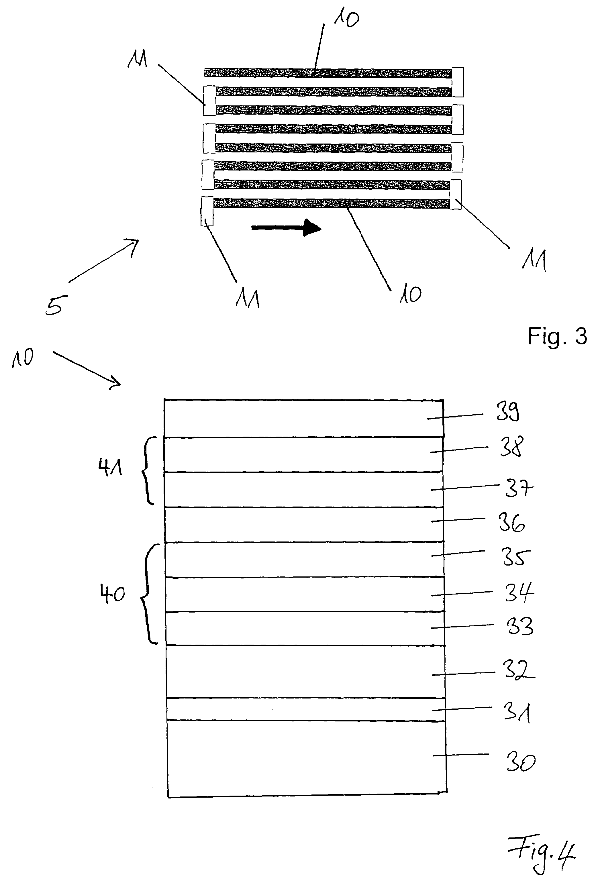
[0025]FIG. 4 shows a magnetoresistive layer system 10 which, in plan view, at least regionally has a strip-type structure. To that end, provided on a customary substrate 30 is a growth layer or a buffer layer 31, on which an anti-ferromagnetic layer 32 is situated. Disposed on this layer 32 is a layer system in the form of an artificial anti-ferromagnet 40 having a first fixed layer 35, i.e., a “pinned” layer or a reference layer, an intermediate layer 34 and a second fixed layer 33. Situated on artificial anti-ferromagnet 40 is a metallic layer 36, and on it a detection layer 41 made up of a first sublayer 37 and a second sublayer 38 is provided. Finally, a customary cover layer 39 made, e.g., of tantalum is located on detection layer 41.

[0026]First fixed layer 35 is made of a first ferromagnetic material, e.g., a CoFe alloy such as Co90Fe10. Second fixed layer 33 is made of a second ferromagnetic material, e.g., likewise a CoFe alloy such as Co90Fe10. Intermediate layer 34 is made...


PUM

PropertyMeasurementUnit
magnetizationaaaaaaaaaa
widthaaaaaaaaaa
widthaaaaaaaaaa

Abstract

A magnetoresistive sensor element is provided, having a magnetoresistive layer system which, in top view, is at least regionally striated. The sensor element operates on the basis of the GMR effect and is constructed according to the spin valve principle, the striated layer system featuring a reference layer having a direction of magnetization substantially uninfluenced by a direction of an outer magnetic field acting on it. During operation, the sensor element provides a measuring signal which changes as a function of a measurement angle between the component of the field strength of the outer magnetic field lying in the plane of the layer system, and the direction of magnetization, and from which this measurement angle is able to be ascertained. In addition, observed in a top view of the striated layer system, the angle between the direction of magnetization in the absence of the outer magnetic field and the longitudinal direction of the striated layer system is set in such a way that in response to an influence of the outer magnetic field having a defined field strength, which is selected from a predefined work interval, the angle error of the layer system, as a function of this angle and the field strength, is minimal.

Description

FIELD OF THE INVENTION[0001]The present invention relates to a magnetoresistive sensor element and a method for reducing the angle error of a magnetoresistive sensor element.BACKGROUND INFORMATION[0002]Because of their enlarged measuring range of 360° and enlarged signal amplitudes and thus lower susceptibility to interference compared to AMR angle sensors, magnetoresistive sensor elements based on the GMR (giant magneto resistance) effect according to the so-called spin valve principle are increasingly being utilized for angle detection in motor vehicles. To that end, the sensor system has a field-generating magnet and an angle sensor, or more generally a magnetoresistive sensor element, positioned in proximity thereto, the direction of the magnetic field acting on this sensor element being detected.[0003]The design of magnetoresistive sensor elements on the basis of the spin valve principle differs from GMR sensor elements or GMR multilayers, which have an alternating sequence of ...

Claims


Application Information

Patent Timeline
Patent Type & Authority Patents(United States)
IPC IPC(8): G11B5/33G11B5/127G01R33/09
CPCG01R33/093B82Y25/00
Inventor SCHMOLLNGRUBER, PETERHERRMANN, INGOSIEGLE, HENRIKKITTEL, HARTMUTFARBER, PAULMAY, ULRICH
Owner ROBERT BOSCH GMBH
Why Eureka
Try Eureka