Supercharge Your Innovation With Domain-Expert AI Agents!

Ring interconnection network system, node equipment, network management equipment, and path setting method

a network system and node technology, applied in the field of node equipment, network management equipment, and path setting method, can solve the problems of difficult to meet the needs of today's carrier operators, complex path restoration process in such a ring interconnection network system, and high cos

Inactive Publication Date: 2006-08-22
KK TOSHIBA
View PDF14 Cites 13 Cited by
  • Summary
  • Abstract
  • Description
  • Claims
  • Application Information

AI Technical Summary

Benefits of technology

[0016]A first object of the present invention is to provide a ring interconnection network system free from a misconnection even when a failure is avoided using a Transoceanic method, and node equipment used in the network system.
[0017]A second object of the present invention is to provide network management equipment which improves a human-machine interface and increases the convenience of the system operation, and a path setting method.
[0022]Use of such means enables a plurality of ring networks to be managed on a single screen systematically. As a result, the operator can monitor or control all the paths on a monitoring screen. Furthermore, the operator can create or delete a path extending over ring networks by clicking on the screen. Moreover, the operator can grasp the restored state of paths together with the restored state by Ring APS. In addition, the operator can manage external commands, such as Lockout / Forced SW / Manual SW performed on ring interworking, in a unified manner by operating on the screen. Consequently, it is possible to improve the human-machine interface.

Problems solved by technology

This prevents operators who offer node equipment from becoming multi-vendors, which means that it is difficult to meet the needs of today's carrier operators.
This takes a lot of time and labor for the operator to do it.
Furthermore, the path restoration process in such a ring interconnection network system is complex.
This makes it more difficult for the operator to grasp the state of each path.
As described above, a failure avoiding method using the Transoceanic method has not been provided in the ring interconnection network system.
As a result, if switching by the Transoceanic method is effected in this type of system, there is a possibility that the line will be disconnected or the traffic will be misconnected.

Method used


Image

  • Ring interconnection network system, node equipment, network management equipment, and path setting method
  • Ring interconnection network system, node equipment, network management equipment, and path setting method
  • Ring interconnection network system, node equipment, network management equipment, and path setting method

Examples


first embodiment

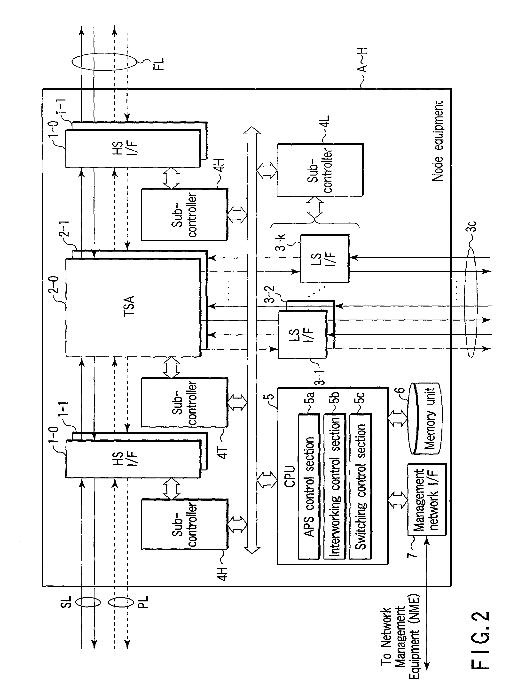
[0125]A first embodiment of the present invention will be explained. In this embodiment, it is assumed that pieces of node equipment (hereinafter, referred to as nodes for the sake of simplicity) A to H each take the configuration of FIG. 2. Before explanation of the parts related to the characteristics of the present invention, general items determined in ITU-T Recommendation G. 842 will be explained.

[0126]Ring interconnection is realized by connecting a plurality of ring networks by means of low-speed optical interfaces (STM-1E / 1o / 4o / 16o / 64o, where the subscript E means an electric interface and the subscript o means an optical interface). Explanation here will be given about a case where the specification described in ITU-T Recommendation G. 842, that is, “Dual Node Ring Interworking,” is applied to the protection architecture of the connection part between ring networks.

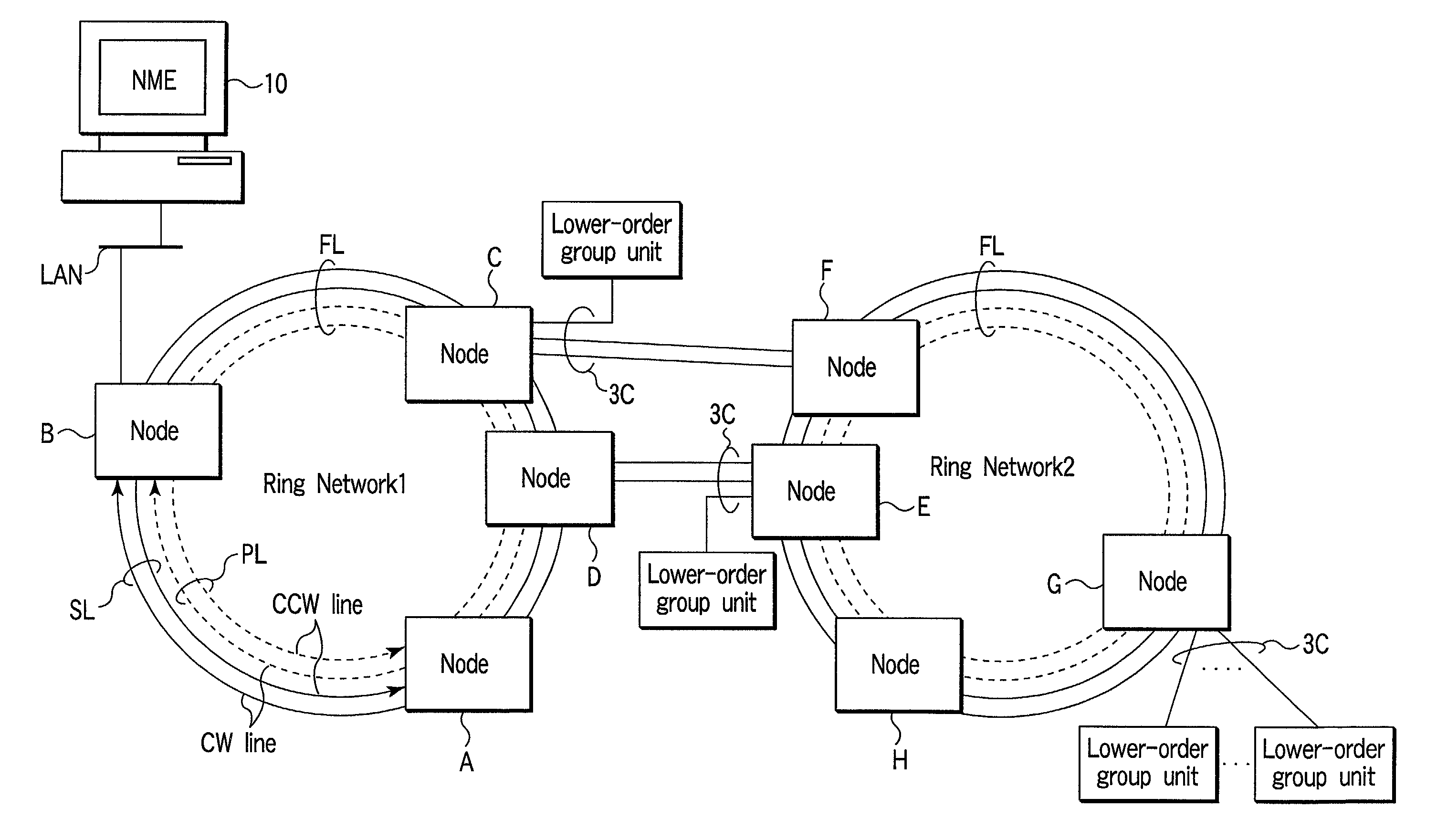
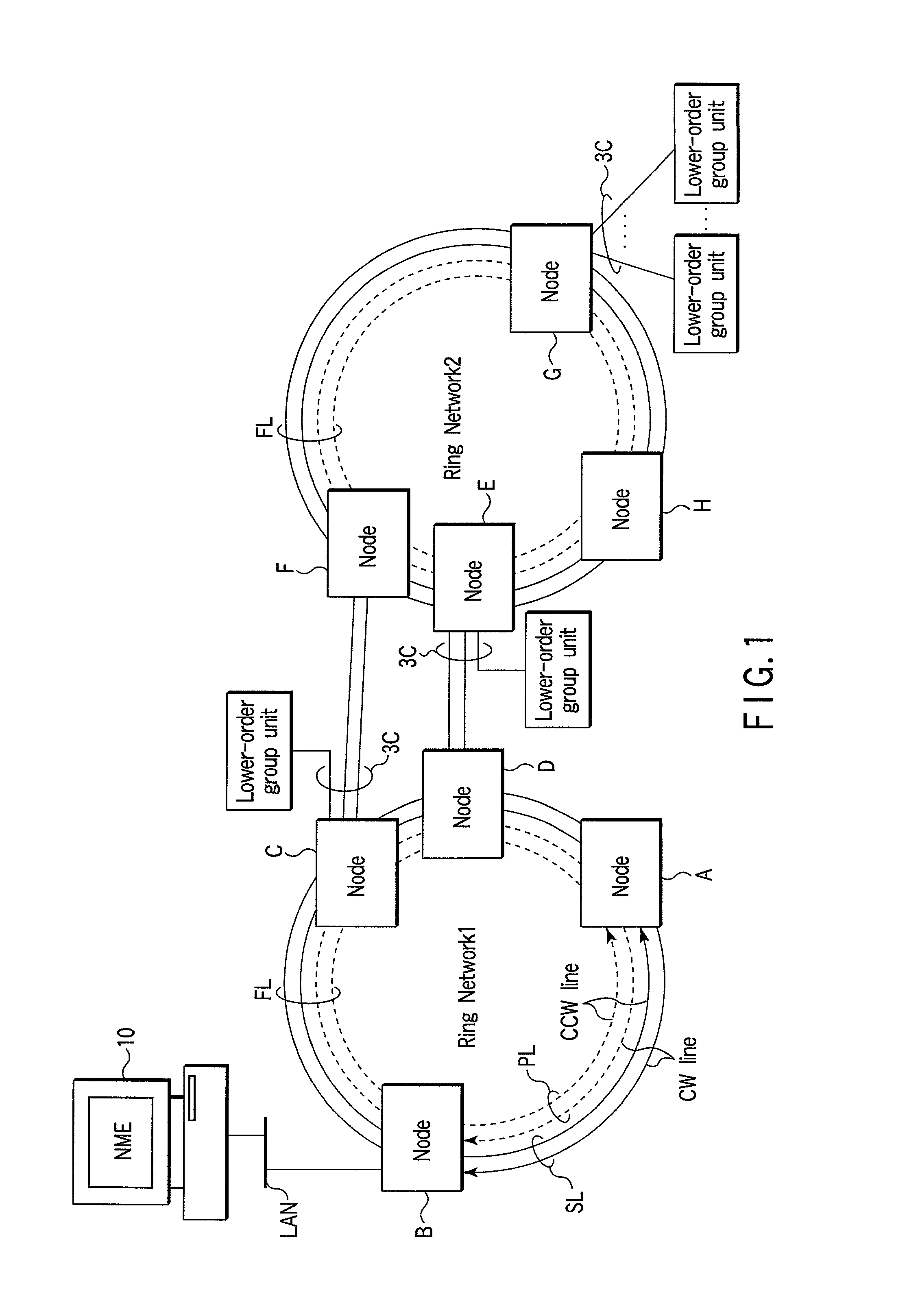
[0127]FIG. 4 is a pictorial view of the system of FIG. 1. Although the system configuration of FIG. 1 is shown...

second embodiment

[0200]A second embodiment of the present invention will be explained. In the second embodiment, the form of a drawing on the display section 25 of NME 10, the control function according to the operation (such as a click operation with a mouse) on its window, and others will be explained. That is, in the second embodiment, a human-machine interface will be explained.

[0201]The individual functions described below are realized mainly by the display control section 110a of NME 10. Specifically, the following functions are realized by putting patches to the control program executed by the CPU 110. The control program is written in a adequate computer language and stored in the memory section 100.

[0202]FIG. 44 shows a window appearing on the display section 25 of NME 10. The window, which is called “Dual Node Interconnection Control Window,” displays the system configuration of FIG. 1 pictorially and graphically using different colors. In the window, an optical fiber line FL connecting a ...

third embodiment

[0253]FIG. 57 shows the configuration of a ring interconnection network according to a third embodiment of the present invention. This system is obtained by interconnecting a plurality of networks (Network A, Network B, and Network C). The networks A, B, and C have nodes A1 to A6, nodes B1 to B6, and nodes Cl to C5, respectively. Node A2 is connected to node B1, node A3 is connected to node B4, and node A5 is connected to node B6 via interconnection lines CL, thereby realizing the interconnection between network A and network B. In addition, node B2 is connected to node Cl, node B3 is connected to node C4, and node B5 is connected to node C6 via interconnection lines CL, thereby realizing the interconnection between network B and network C.

[0254]The individual nodes are connected to each other via bidirectional service lines SL and protection lines PL. Therefore, the configuration of each of the networks A, B, and C is a so-called 4-fiber ring.

[0255]In FIG. 57, a unidirectional path...


PUM


Abstract

A Protection Primary state is newly defined. When the traffic route is switched by a ring interworking function, while APS is in operation, a protection primary node is caused to restore the service path.

Description

CROSS-REFERENCE TO RELATED APPLICATIONS[0001]This application is based upon and claims the benefit of priority from the prior Japanese Patent Applications No. 2000-361831, filed Nov. 28, 2000; and No. 2000-387402, filed Dec. 20, 2000, the entire contents of both of which are incorporated herein by reference.BACKGROUND OF THE INVENTION[0002]1. Field of the Invention[0003]This invention relates to a ring interconnection network system formed by connecting a plurality of ring networks with a self-healing function to each other, node equipment and network management equipment and a path setting method used in the system. This type of network architecture is known as Ring Interconnection or Ring Interworking, which has been described in, for example, ITU-T (Telecommunication Standardization Sector of ITU) Recommendation G. 842 distributed by the ITU (International Telecommunication Union).[0004]2. Description of the Related Art[0005]A traffic self-healing method that is completed in a ri...

Claims


Application Information

Patent Timeline
IPC IPC(8): H04L12/26H04J3/08H04L12/24H04L12/437H04Q11/04
CPCH04J3/085H04L41/0663H04L12/437H04J2203/0042H04J2203/006H04J2203/0057Y04S40/00
Inventor SUETSUGU, HIROMUNEBABA, KENJISUZUKI, MASATOSHI
Owner KK TOSHIBA
Features
  • R&D
  • Intellectual Property
  • Life Sciences
  • Materials
  • Tech Scout
  • Unparalleled Data Quality
  • Higher Quality Content
  • 60% Fewer Hallucinations
Learn More