Near-field X-ray fluorescence microprobe

Active Publication Date: 2006-08-22
CARL ZEISS X RAY MICROSCOPY
View PDF7 Cites 42 Cited by
  • Summary
  • Abstract
  • Description
  • Claims
  • Application Information

AI Technical Summary

Benefits of technology

[0018]Generally, a proximity control system is used with the target to control a distance between the target and a surface of the sample. It senses the distance and then feed the sensed distance to an actuation system to enable closed-loop control of the distance.
[0019]The above and other features of the invention including various novel details of construction and combinations of parts, and other advantages, will

Problems solved by technology

This effect results in an unstable atomic state, and the outer shell electrons can transfer to this lower energy shell by a radiative process.
The presence of this background Bremstrahlung radiation makes it extremely difficult to de

Method used


Image

  • Near-field X-ray fluorescence microprobe
  • Near-field X-ray fluorescence microprobe
  • Near-field X-ray fluorescence microprobe

Examples


Embodiment Construction

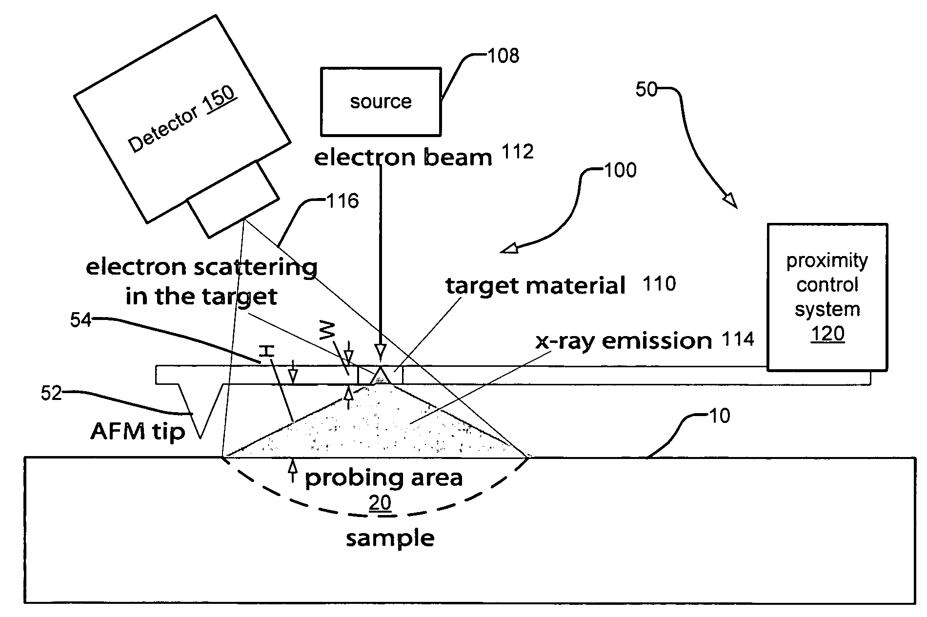
[0027]The invention concerns an x-ray microprobe that has an x-ray target that is placed in close proximity to the sample and specifically the sample surface. An energetic beam, for example a focused electron beam, focused x-ray beam, or focused ion beam, then strikes the target to generate the x-ray emission.

[0028]The emitted x-rays are then used as a microprobe to excite fluorescence emission from the sample.

[0029]FIG. 4 illustrates an AFM 50 with integrated x-ray microprobe 100 that has been constructed according to the principles of the present invention.

[0030]The AFM 50 comprises a tip 52, such as a tiny shard of diamond, that has been bonded to a cantilevered arm 54, such as a strip of gold foil. More commonly, the tip / arm assembly is fabricated from silicon or silicon nitride using micro electromechanical systems (MEMS) fabrication processes.

[0031]In typical operation, the tip 52 at the end of the cantilever arm 54 was pressed against the surface of the sample 10 while the sa...


PUM


Abstract

This invention pertains to an x-ray microprobe that can be placed very close the sample surface. A practical implementation is an x-ray target material integrated to an atomic force microscope (AFM) tip and an electron beam is focused to the target materials to generate x-ray emission. This microprobe can be combined with energy-resolved detector or a fluorescence imaging system for material analysis applications.

Description

RELATED APPLICATIONS[0001]This application claims the benefit under 35 USC 119(e) of U.S. Provisional Application No. 60 / 591,809, filed Jul. 28, 2004 which is incorporated herein by reference in its entirety.BACKGROUND OF THE INVENTION[0002]X-ray fluorescence is a powerful technique for material composition analysis in many industrial and research applications. X-ray fluorescence results when an electron makes a transition from a high atomic orbit to a lower one. With sufficient energy, the excitation radiation, such as x rays, energetic electrons, or ions, eject inner shell electrons by means of photo-electric effect to create a vacancy in the inner shell. This effect results in an unstable atomic state, and the outer shell electrons can transfer to this lower energy shell by a radiative process.[0003]FIG. 1 illustrates the radiative process with respect to the K (left) and L (right) line emissions from a titanium atom. Left: a vacant K shell can be filled by an electron making a t...

Claims


Application Information

Patent Timeline
IPC IPC(8): G01N23/223G01T1/36
CPCG01N23/223G01N2223/076Y10S977/863Y10S977/95
Inventor YUN, WENBING
Owner CARL ZEISS X RAY MICROSCOPY
Why Eureka
Try Eureka