Furnace heat exchanger

Inactive Publication Date: 2006-08-29
CARRIER CORP
View PDF16 Cites 32 Cited by
  • Summary
  • Abstract
  • Description
  • Claims
  • Application Information

AI Technical Summary

Benefits of technology

[0013]Briefly, in accordance with one aspect of the invention, the heat exchanger surface area, per unit height of a multipass heat exchanger, is increased by providing wavy cross-sectional shapes in the sides of at least two of the passes. Optimal efficiency is obtained while maintaining the pressure dro

Problems solved by technology

Further, there are required performance and durability requirements for the heat exchanger panels themselves.

Method used


Image

  • Furnace heat exchanger
  • Furnace heat exchanger
  • Furnace heat exchanger

Examples


Embodiment Construction

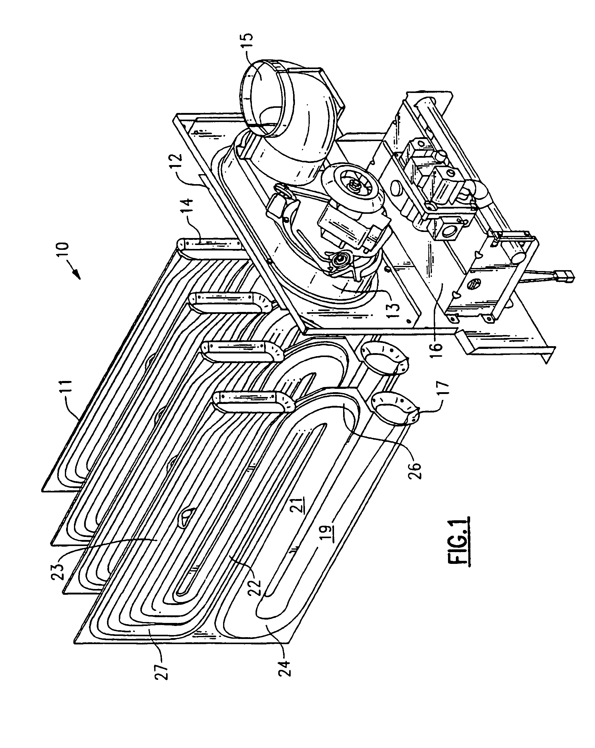
[0032]Referring now to FIG. 1, the invention is generally shown as part of a furnace system including a bank 10 of heat exchanger panels 11. A collector box 12 is connected to an inducer 13 in such a way as to permit the drawing of heated flue gases through the heat exchanger panels 11. That is, the outlets 14 of the heat exchanger panels 11 are connected directly to the collector box 12, where a vacuum is drawn by the inducer 13, with the flue gases being exhausted out a vent by way of the elbow 15.

[0033]At the other end of the heat exchanger panels 11, a burner assembly 16 is provided for purposes of combusting the fuel and air mixture, with the flame extending into the heat exchanger panels 11. For that purpose, individual burners in the burner assembly 16 are aligned with the inlet ends 17 of the heat exchanger panels.

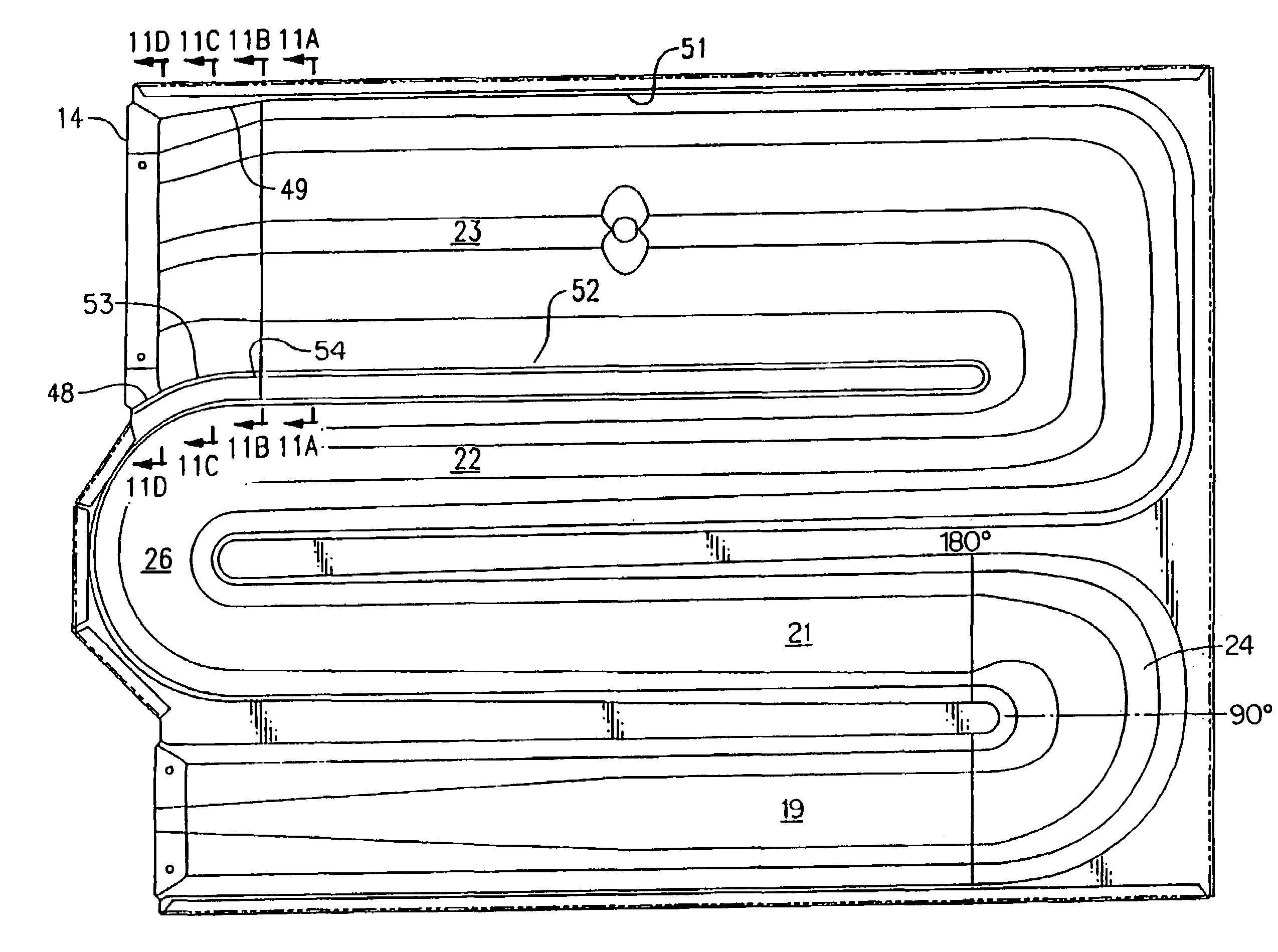
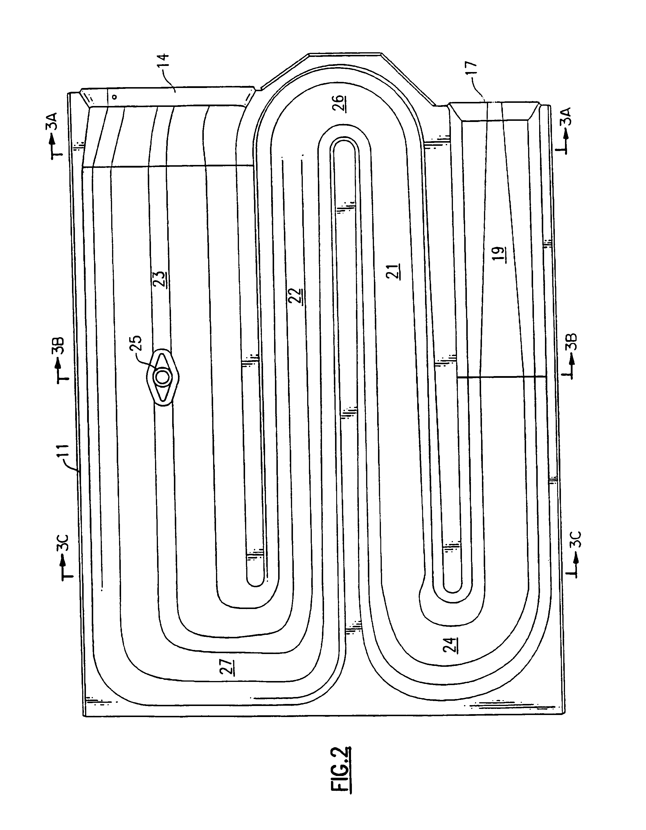
[0034]Referring now to FIGS. 1–3, a heat exchanger panel 11 is shown to include a first pass 19, a second pass 21, a third pass 22, and a fourth pass 23, all inter...


PUM


Abstract

A furnace heat exchanger with multiple parallel flow passages wherein the last flow passage extends downwardly from its plane as it approaches the outlet so as to result in a lower overall height of the heat exchanger. Preferably both the upper wall and the lower wall of the last passage extend downwardly such that the cross-sectional area of the last flow passage is not reduced and is preferably increased as it approaches the outlet. The bottom wall extension is preferably curvilinear and has substantially the same curvature as a return bend at the inlet of the penultimate flow passage.

Description

BACKGROUND OF THE INVENTION[0001]This invention relates generally to furnaces and, more particularly, to multipass heat exchangers therefor.[0002]A typical residential furnace has a bank of heat exchange panels arranged in parallel relationship such that the circulating blower air passes between the panels to be heated before it passes to the distribution duct. Each of the panels is typically formed of a clamshell structure which has an inlet end into which the flame of a burner extends to heat the flue gas, an outlet end which is fluidly connected to an inducer for drawing the heated flue gas therethrough, and a plurality of legs or passes through which the heated flue gas passes. In order to obtain the desired high efficiencies of operation, it is necessary to maximize the heat transfer that occurs between the heated flue gas within the heat exchanger passes and the circulating air passing over the outer sides of the heat exchanger panels. Further, there are required performance a...

Claims


Application Information

Patent Timeline
IPC IPC(8): F24H3/10F28F13/08
CPCF24H3/105F28F13/08F28D9/0031F28F2250/102
Inventor ZIA, NINEV KARLMANOHAR, SHAILESH SHARADBECK, SCOTT ANDREW
Owner CARRIER CORP
Why Eureka
Try Eureka