[0007]Under the circumstances, this invention was made. Accordingly, an object of the present invention is to provide, as a drill bit for use in drilling holes in materials such as concrete and stone, a drill bit whose drilling function easily stands comparison with that of conventional drill bits, which is simple in design to provide improved productivity, and which is high in bit body rigidity to provide improved durability, which is particularly suitable for drill bits for drilling holes of small
diameter.
[0010]In accordance with the drill bit constructed in the way as described above, when drilling holes in materials such as concrete and stone, there is defined a larger clearance between the bit body formed into a straight configuration having an approximately polygon In accordance with the drill bit constructed in the way as described above, when al cross section and a
drill hole in comparison with drilling by a convention drill bit having a circular cross section. Accordingly, the motion of the drill bit in the longitudinal direction of the shaft also helps
powder / particle-like chips created at the tip end to travel upward from the tip end through the clearance and to be smoothly ejected out of the
drill hole.
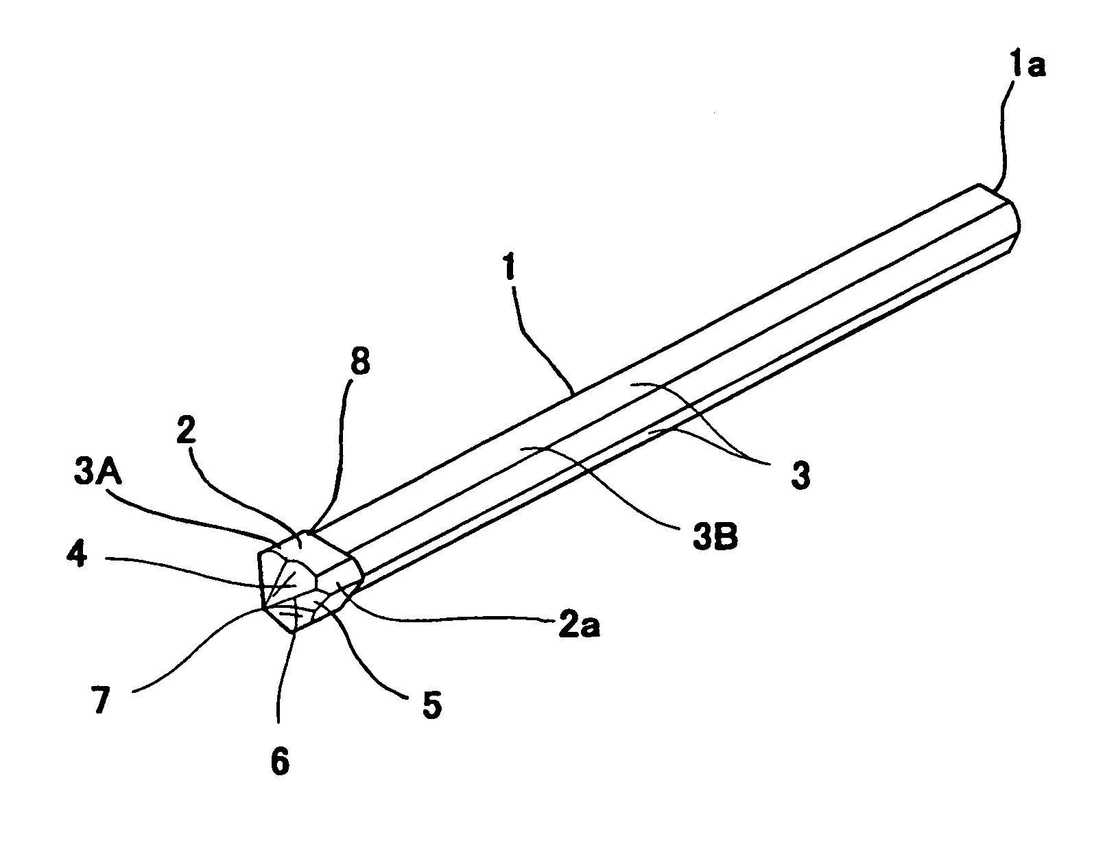
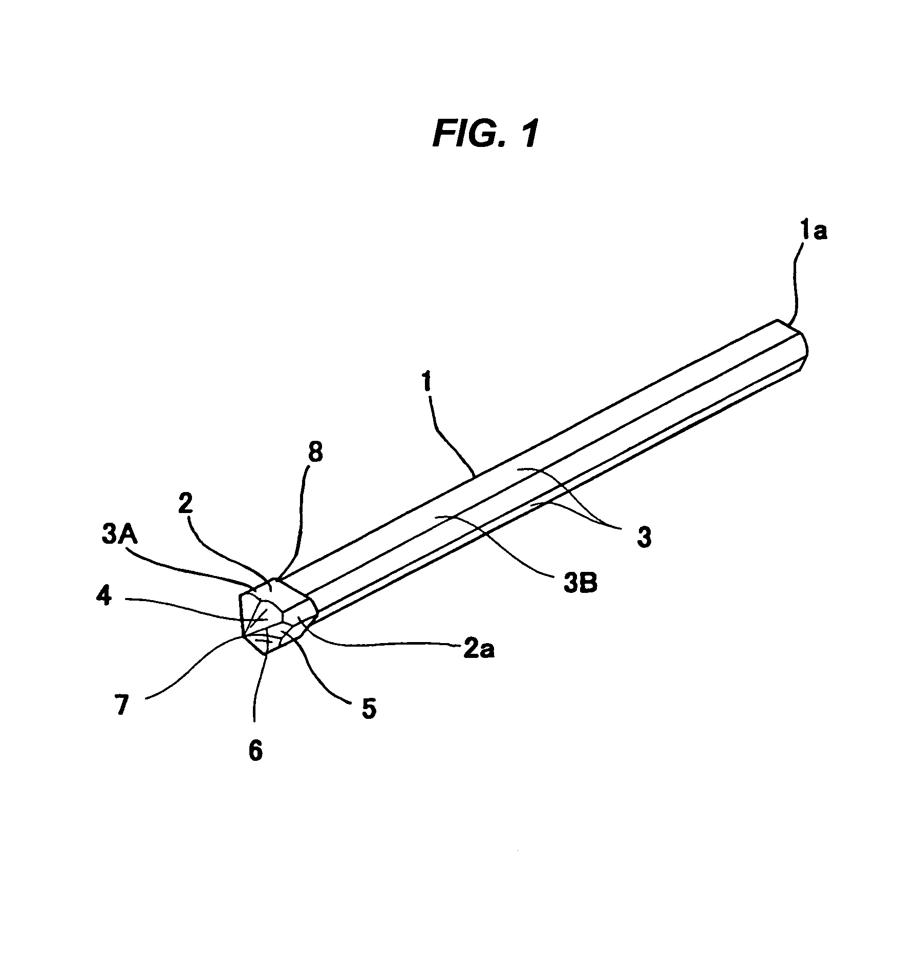
[0011]Therefore, the drilling function of the drill bit formed in accordance with the present invention is in no way inferior to that of conventional drill bits. Further, the drill bit of the present invention is manufactured just by tightly uniting a cutting blade tip comprising a block body to the tip end of a bit body of a given length which has no
chip ejection groove and which is formed into a straight configuration having an approximately polygonal cross section, thereby being superior in productivity at the time of manufacture. Further, since the bit body has a straight configuration having an approximately polygonal cross section and differs from conventional ones in that it has no
chip ejection groove having a rectangular cross section, this makes it possible to eliminate a “notch effect” known in the field of the
strength of materials. Accordingly, the drill bit of the present invention will not undergo a drop in the rigidity in comparison with conventional drill bits and is therefore particularly suitably used as a drill bit for small
diameter hole drilling which is susceptible to breakage during drilling operations. And, the drill bit of the present invention is less subject to breakage and is superior in durability, regardless of small
diameter or large diameter, and the present invention provides drill bits (products) of high quality. Furthermore, as described above, the drill bit of the present invention is suitable for improving productivity and can be provided inexpensively.
[0012]If the drill bit of the present invention employs such a construction that three cutting blade portions are formed around the cutting blade tip so that its bit body is formed into a straight configuration having an approximately triangular cross section, this makes it possible to provide a practically optimal embodiment manner in which rotation during drilling is well balanced, each cutting blade portion exhibits effective cutting properties, and the bit body exhibits highly reliable rigidity.
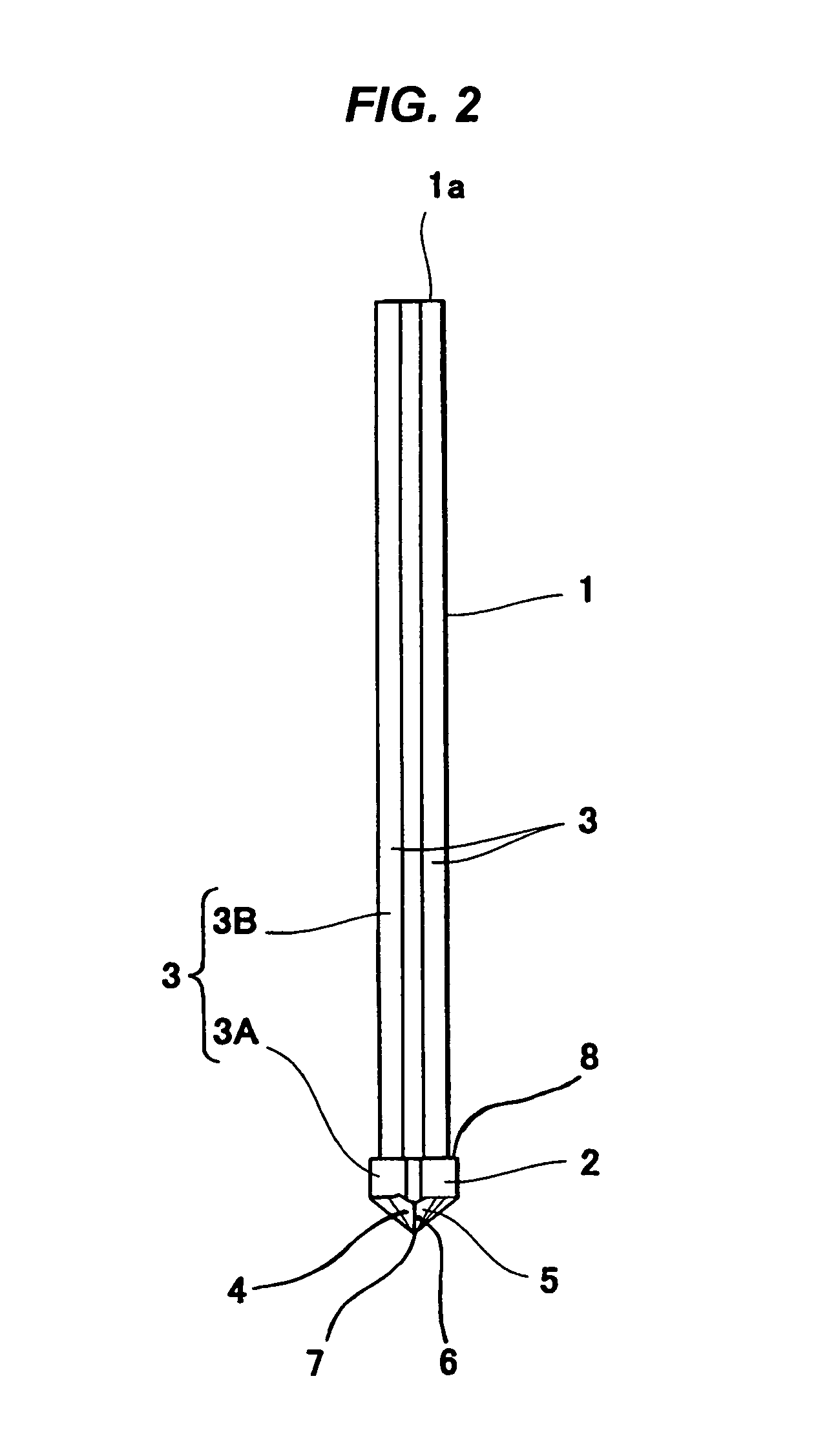
[0014]Furthermore, if the drill bit described above employs such a construction that a connecting line of a cutting surface and a flank surface which are formed in each cutting blade portion of the cutting blade tip acts as a cutting edge and these cutting edges are connected together at a blade tip point so that the blade tip point is shaped like a peak without any
chisel point, adjoining cutting edges of these cutting edges cooperate to effectively crush chips of
large size created in the cutting surface of a
drill hole into
small particles. This provides a construction capable of reducing biased resistance that the blade tip will receive, of making the drill bit free from run-out, and of enabling the blade tip point shaped like a peak to always lie in the center of the cutting surface of the drill hole. As a result, the roundness of drill holes drilled by the drill bit of the present invention is improved and it becomes possible to drill constant-diameter holes at high accuracy.
[0015]Further, the drill bit of the present invention may employ such a construction that, as in a general-purpose drill, a standardized shank is additionally formed at a base portion of the bit body. In such a case, it is possible to adequately change and attach drill bits of different diameters to a
drive shaft (a single rotary hammer drilling machine) as a common drill bit
mount. This therefore provides a drill bit capable of quick change. However, even for the case of a drill bit of the present invention without additional formation of a shank, it is possible to directly and readily hold (connect) the base portion of the bit body formed into a straight configuration having a polygonal cross section by a chuck structure mounted onto the
drive shaft of a general rotary
hammer drill. In this case, since it is sufficient that a base potion of the bit body of the drill bit be simply
cut to a desired length to form a sectional end, it is possible to reduce the number of process steps required in the manufacture of drill bits, to save material, and to provide inexpensive drill bits. Additionally, the weight of a drill bit itself is reduced, thereby improving portability.

