Method of manufacturing electroluminescence panel

a technology of electroluminescence and manufacturing method, which is applied in the manufacture of electrode systems, cold cathode manufacturing, electric discharge tube/lamp manufacture, etc., can solve the problems of difficult to maintain a gap between substrates, come in contact with elements, and significantly deteriorate organic el elements, etc., to achieve the effect of reliably protecting organic el elements

Inactive Publication Date: 2006-08-29
SANYO ELECTRIC CO LTD
View PDF11 Cites 30 Cited by
  • Summary
  • Abstract
  • Description
  • Claims
  • Application Information

AI Technical Summary

Benefits of technology

[0013]The present invention is made in view of the foregoing disadvantages and aims to provide a simple manufacturing method capable of securing a sealed space for reliably protecting the organic EL elements or the like between an element substrate and an opposing substrate.
[0018]In this manner, in a vacuum, a drop of sealing liquid such as silicon oil is applied onto the panel region and the element substrate and the opposing substrate are adhered together with a sealing member. Therefore, the necessity of forming an injection opening in the sealing member can be eliminated. The sealing member is formed in a jointless manner and therefore requires no sealing operation of the injection opening. Further, because the substrates are bonded together in a vacuum, even when some space is formed between the substrates and the sealing liquid, such a space would disappear when the substrates are returned to a normal atmosphere. Accordingly, an organic EL panel can be manufactured using a very effective lamination operation.

Problems solved by technology

In such an organic EL panel, moisture must be excluded because the organic EL elements will significantly deteriorate if exposed to moisture.
However, with the above-described configuration in which dry nitrogen is enclosed between the opposing substrate 60 and the element substrate 10, it is difficult to maintain a gap between the substrates in the sealed space where nitrogen only exists, and this may cause the opposing substrate 60 to come in contact with the elements and damage them when the opposing substrate 60 is deformed due to external pressure or the like.
These problems are likely to occur as the panel size increases.
When silicon oil is injected, on the other hand, it is necessary to seal the injection opening formed in part of the UV sealing member 66 after injection, which complicates the assembly and manufacturing procedures.
Further, when dry nitrogen is enclosed between the opposing substrate 60 and the element substrate 10 according to the above-described manufacturing method, there is a possibility that an excessive amount of nitrogen gas may be enclosed in the sealed space, for example, due to misalignment in bonding the two substrates.
Enclosure of excessive nitrogen would increase the pressure in the sealed space of the panel, leading to a problem that the opposing substrate 60 is likely to be unstuck from the element substrate.

Method used


Image

  • Method of manufacturing electroluminescence panel
  • Method of manufacturing electroluminescence panel
  • Method of manufacturing electroluminescence panel

Examples


Embodiment Construction

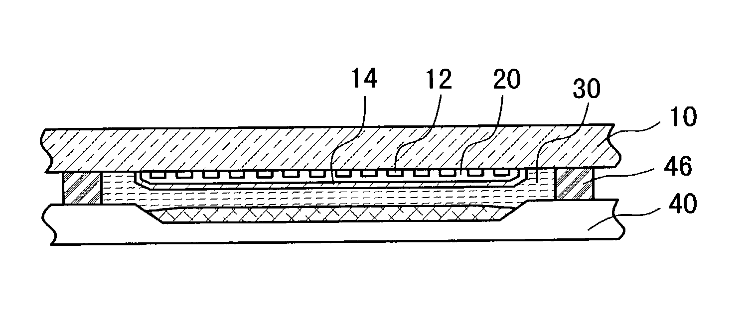
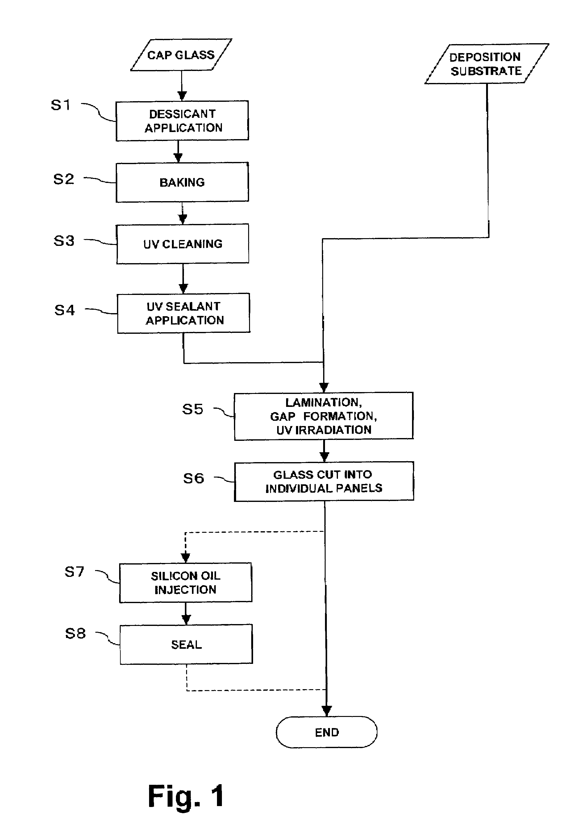
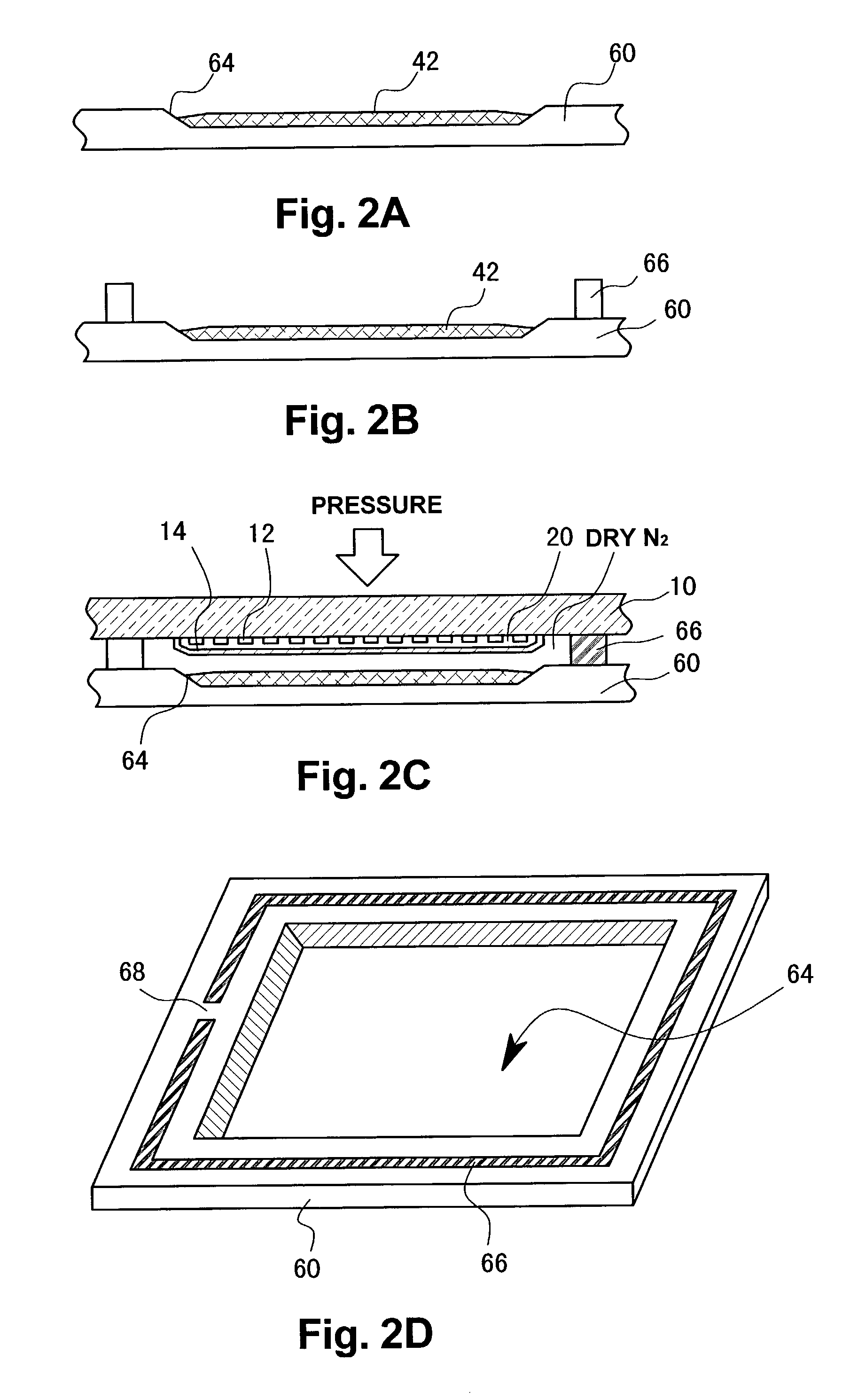
[0029]A method of manufacturing an organic EL panel according to an embodiment of the present invention will be described with reference to FIGS. 4, 5A to 5D, 6A, 6B, and 7A to 7C. First, an opposing substrate (cap glass: sealing substrate) 40 is prepared and a paste of a desiccant 42 is applied to the substrate 40 (S11). A desiccant paste is a solvent containing a mixture of Ba oxide, Ca oxide or the like. As shown in FIG. 5A, an etching pocket 44 is formed in the panel region of the cap glass 40 by etching, and the desiccant 42 is applied to this etching pocket 43. Then, the whole product is baked at about 140° C. or more in an oven (S12). As a result, a solvent or the like evaporates from the desiccant 42 and the desiccant 42 is activated. Next, a surface of the substrate 40 is cleaned with UV irradiation having an energy of 10 mW / cm2 or greater. Thereafter, a UV sealing member 46 is applied to the substrate 40 such that it projects from a planar surface of the cap glass 40. More...


PUM


Abstract

An opposing substrate which is subjected to desiccant application, baking, UV cleaning, UV sealant application, or the like and an element substrate having EL elements formed thereon are affixed together by applying a sealing liquid such as silicon oil in a vacuum. Subsequently, when exposed to a normal atmosphere, the opposing substrate and the element substrate are adsorbed to each other while a predetermined gap is maintained in between. In this state, the UV sealant is cured with UV irradiation. It is thus possible to enclose the sealing liquid between the opposing substrate and the element substrate using a simple manufacturing method.

Description

BACKGROUND OF THE INVENTION[0001]1. Field of the Invention[0002]The present invention relates to a method of manufacturing an organic EL panel, in which an EL (electroluminescence) element substrate having a plurality of EL elements formed thereon and an opposing substrate facing the EL element substrate are laminated together to form an organic EL panel.[0003]2. Description of Related Art[0004]Conventionally, organic EL (ElectroLuminescence) panels, one type of flat display device, have attracted attention as self-emissive display panels. An organic EL panel is produced by first forming a large number of EL elements on a glass substrate (an element substrate) by evaporation of various materials and then laminating an opposing substrate (cap glass, sealing substrate) onto an element forming surface of the element substrate. In such an organic EL panel, moisture must be excluded because the organic EL elements will significantly deteriorate if exposed to moisture. Further, in order t...

Claims


Application Information

Patent Timeline
Patent Type & Authority Patents(United States)
IPC IPC(8): H05B33/10H01J9/40H01L51/56H05B33/04H01L51/52
CPCH01L51/5237H01L2251/566H10K50/846H10K50/841H10K71/851H05B33/04
Inventor MATSUOKA, HIDEKI
Owner SANYO ELECTRIC CO LTD
Why Eureka
Try Eureka