[0007]It is therefore an object of the present invention to provide a filter for use with a pulse wave sensor in determining accurately a rising point of a pulse wave, and a pulse wave analyzing apparatus that can accurately determine the rising point of pulse wave.
[0008]The Inventors have carried out extensive studies to achieve the above-indicated object, and have found the following facts: A pulse wave, that is, a composite wave of an
incident wave traveling from subject's heart to his or her
peripheral-side portion and a reflected wave produced when the
incident wave is reflected by a bifurcated portion of the
peripheral side, has such features that the
incident wave shows a sharp rising portion since it is produced when blood is ejected from the heart whereas the reflected wave shows a gentle rising portion since its high-frequency component is attenuated during propagation through
artery and its low-frequency component is relatively enhanced. Therefore, a gentle rising portion of a pulse wave is caused by its reflected wave component and, if the reflected wave component is removed from the pulse wave, its incident wave component is relatively enhanced and the rising portion of the pulse wave is sharpened, so that the accuracy of determination of the rising point is improved. The present invention has been developed on this finding.
[0010]According to the first aspect of the present invention, the pulse wave represented by the signal filtered by the present filter has such features that the reflected wave component as the low-frequency component has been removed and the incident wave component has been enhanced. Therefore, the pulse wave represented by the filtered signal shows a sharp rising portion. Thus, the time of rising point of the pulse wave can be accurately determined based on the signal filtered by the filter.
[0011]An average frequency of a reflected wave component of a pulse wave be experimentally determined, in advance, and the filter according to the first aspect of the present invention can be adapted to have a low-side
cut-off
frequency band whose upper limit is determined based on the average frequency. In this case, the accuracy of determination of rising point is improved. However, the frequency of reflected wave component differs among individual patients or among different body portions of each patient. Hence, a pulse wave analyzing apparatus according to a second aspect of the present invention employs a plurality of filters having respective low-side
cut-off frequency bands differing from each other, determines respective times of respective rising points of respective pulse
waves represented by the respective signals filtered by the filters, and determines a time of a single rising point by comparing the thus determined respective times of respective rising points with each other.
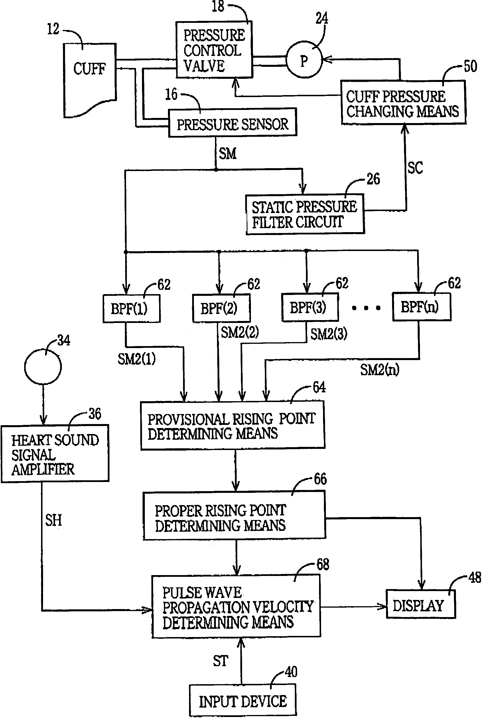
[0013]According to the second aspect of the present invention, the provisional rising point determining means determines the respective times of respective provisional rising points of respective pulse
waves represented by the respective signals that have passed through the filters having the respective different low-side
cut-off frequency bands, and the proper rising point determining means compares the respective times of respective provisional rising points with each other and thereby determines the time of proper rising point based on the respective times of respective provisional rising points. Therefore, even if respective rising portions of respective reflected wave components and / or respective incident wave components of respective pulse waves detected from different patients or different body portions of each individual patient may have different frequencies or different frequency bands, the present pulse-wave analyzing apparatus can accurately determine a time of a rising point of a pulse wave detected from each of the patients or each of the body portions of each individual patient.
[0014]According to a first feature of the second aspect of the present invention, the proper rising point determining means determines, when at least two times of the, respective times of detection of the respective provisional rising points are substantially equal to each other, the at least two times substantially equal to each other, as the time of detection of the proper rising point. The respective pulse waves represented by the respective signals filtered by the filters having the respective different low-side cut-off frequency bands, show respective sharp rising portions similar to each other, if respective upper limits of the respective low-side cut-off frequency bands of the filters are higher than the frequencies of the respective reflected wave components of the respective pulse waves. Therefore, the respective times of respective rising points of those sharp rising portions are substantially equal to each other. Thus, the present apparatus can accurate determine a time of a rising point of a pulse wave.

