Process for fabricating metal spheres

a metal sphere and process technology, applied in metal-working apparatuses, transportation and packaging, other domestic objects, etc., can solve the problems of inability to meet the requirements of production, so as to facilitate the process of the present invention and achieve the effect of not affecting the production throughput of metal spheres

Inactive Publication Date: 2006-08-29
ACCURUS SCI
View PDF56 Cites 7 Cited by
  • Summary
  • Abstract
  • Description
  • Claims
  • Application Information

AI Technical Summary

Benefits of technology

[0007]It is a further objective of the present invention to provide a process by which the degree of deviation from a perfect spherical shape of the metal spheres can be minimized.
[0008]It is an additional objective of the present invention to provide a process by which the size of the metal spheres can be determined within a small tolerance.
[0011]It is a further objective of the present invention to provide a process by which throughput of the metal spheres is not hampered by the precision achieved in the finished product.
[0012]It is also an objective of the present invention to provide an apparatus that facilitates the process of the present invention.
[0014]Instead of disturbing the steady flow of the molten metal stream to create droplets, the method of the present invention utilizes a fast vibratory piston to strike each individual droplet out through a nozzle. Driven in this manner, the droplets can be shot initially upward through a cooling medium and spend more time passing through the medium before solidification of each droplet begins. Thus, a shorter cooling tower can be used, thereby saving costs related to the height of the manufacturing room, as well as reducing the amount of coolant required during the solidification process. As the piston slams a stopper or withdraws its direction of motion quickly, the resulting sudden impact transfers the energy at the piston to the molten metal and creates a droplet that shoots out through the nozzle. Control of the striking force of the piston against the stopper and knowledge of the size of the aperture in the nozzle, allow droplets of molten metal having precisely-controlled volumes to be separated from the molten metal mass and propelled through the cooling medium allowing for the formation of spheres of uniform size.
[0016]A gas screen gate is disposed beneath the buffering chamber. This gate is a large hollow disc with two openings, one each at the centers of both top and bottom faces of the circular disc. One or more fans are disposed inside the disc along the edge of the disc wall. The fan blows in a direction tangential to the circular wall, causing the gas within the disc to flow in a circular direction within the hollow interior of the disc. This movement creates a gas barrier that slows down the heat exchange rate between the buffer chamber and the top end of the cooling tower so that the droplets do not experience quick cooling while still in the buffering chamber. The two openings in the gate allow the droplets to pass out of the buffering chamber under the force of gravity.

Problems solved by technology

This mechanical method has intrinsic limitations that result in coarse dimensional tolerances, because each mechanical operation adds a certain amount of deviation to the size and uniformity of the particles, which together produce an unacceptable cumulative effect.
In many cases, these processes can only reach a quasi-steady-state, which limits the production throughput as well as the quality of the resulting spheres.

Method used


Image

  • Process for fabricating metal spheres
  • Process for fabricating metal spheres
  • Process for fabricating metal spheres

Examples


Embodiment Construction

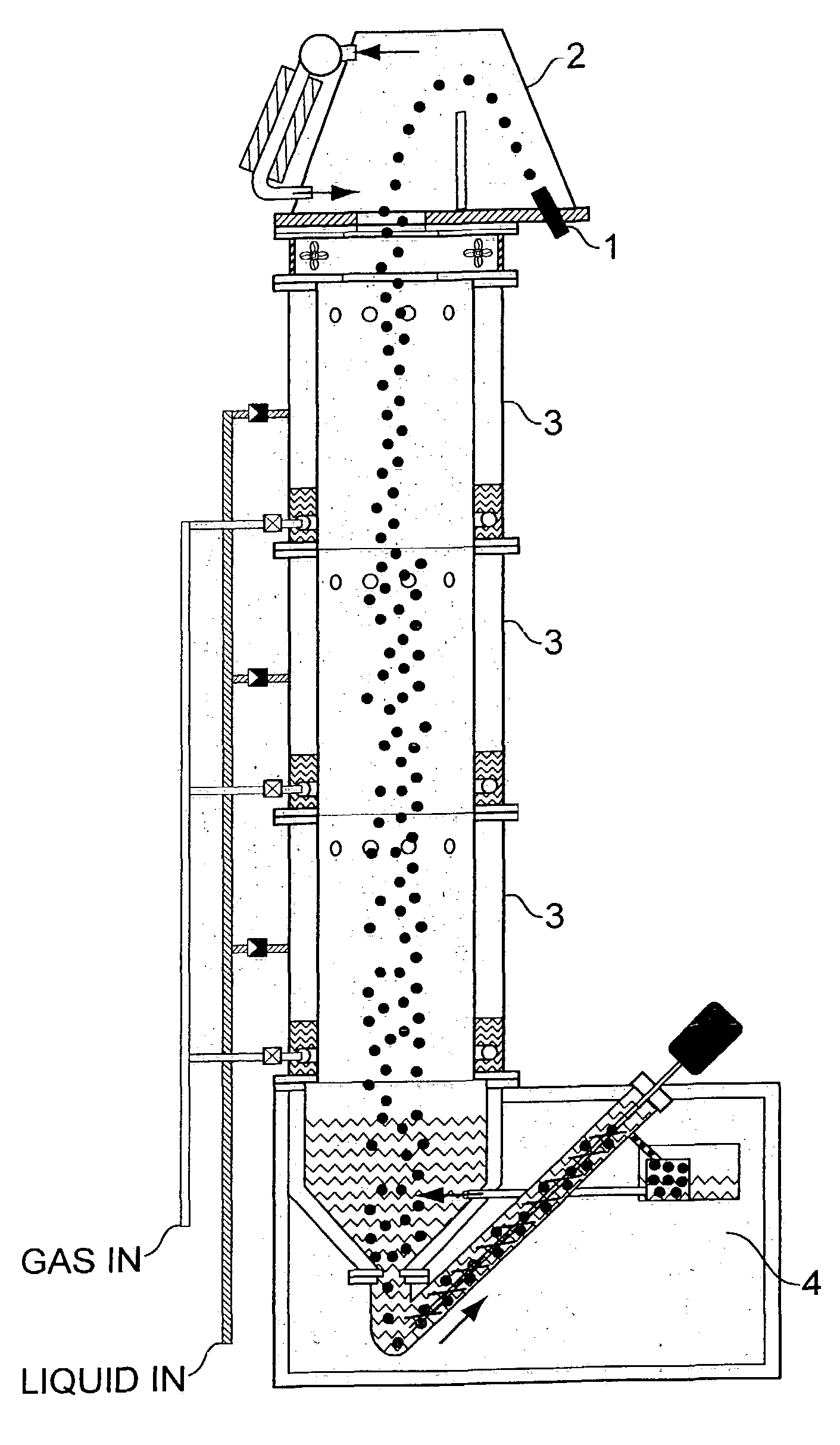
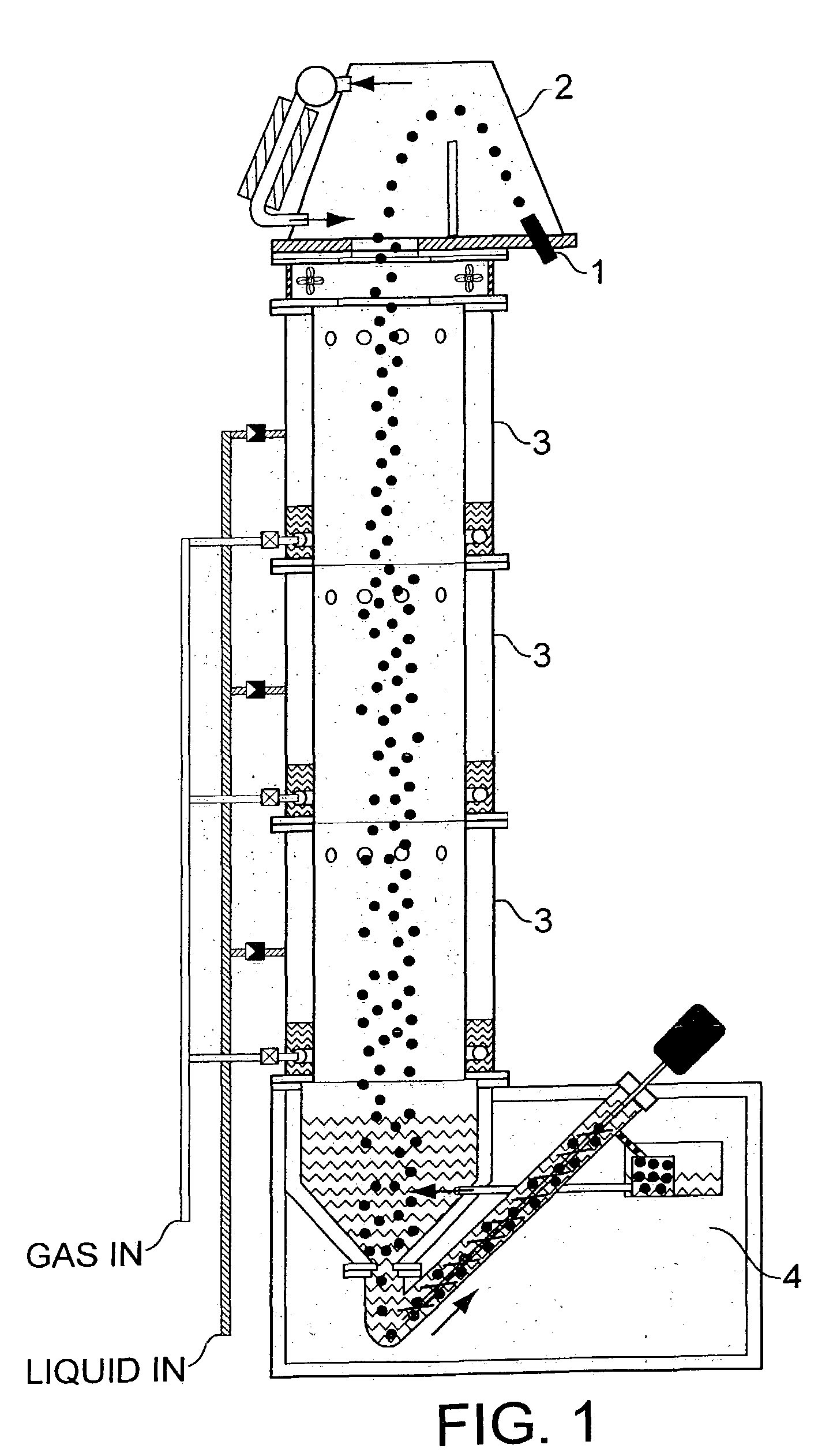
[0044]The present invention provides a process by which metal spheres can be fabricated. As shown in FIG. 7, the process begins with the formation of molten metal droplets 71. The droplets undergo a buffering action 72 to reduce the internal kinetic energy of the droplets prior to final cooling of the droplets to a solid form. Once the internal kinetic energy has been reduced a sufficient amount, the cooling process 73 can begin. Because the internal kinetic energy of the droplets has been reduced at this point, a droplet will form a spherical shape as it cools, due to the surface tension of the molten metal material. After cooling for a sufficient amount of time, the droplets become solid spheres 74, and are collected 75.

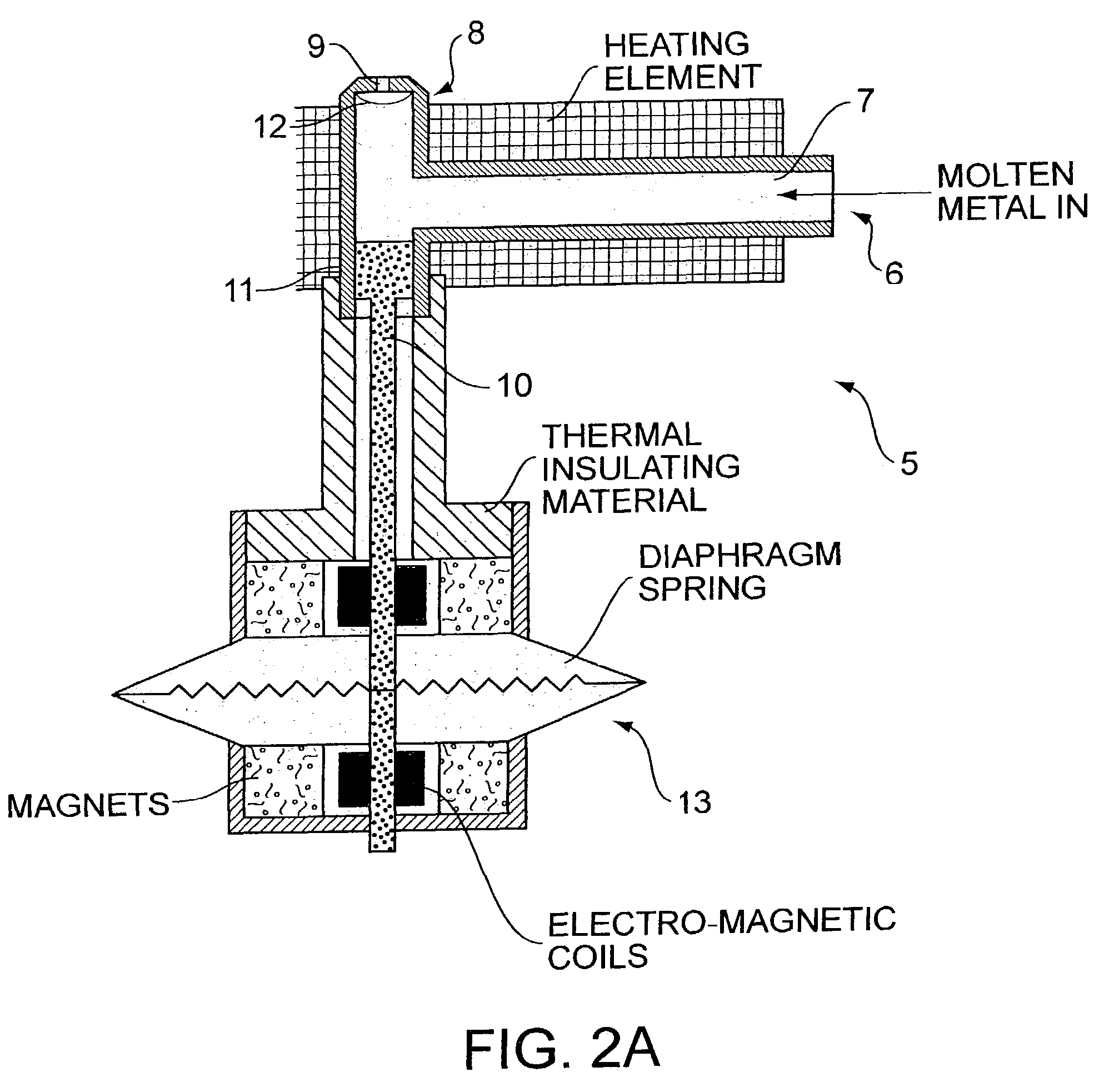
[0045]As shown in FIG. 8, the droplets are formed by providing a mass of molten metal, and exerting an impulse force to the mass of molten metal. The molten metal mass is constrained within a fixed volume 710, which is provided with a single outlet aperture 711. Th...


PUM

PropertyMeasurementUnit
temperatureaaaaaaaaaa
sizeaaaaaaaaaa

Abstract

A method of forming metal spheres includes ejecting a precisely measured droplet of molten metal from a molten metal mass, buffering the molten metal droplet to reduce the internal kinetic energy of the droplet without solidifying the droplet and cooling the buffered droplet until the droplet solidifies in the form of a metal sphere. An apparatus for fabricating metal spheres includes a droplet generator that generates a droplet from a molten metal mass, a buffering chamber that receives the droplet from the droplet generator, and diminishes internal kinetic energy of the droplet without solidifying the droplet, and a cooling drum that receives the droplet from the buffering chamber, and cools the droplet to the extent that the droplet solidifies into a metal sphere. The apparatus may further include a collector arrangement that receives the metal spheres from the cooling drum and makes the metal sphere available for collection.

Description

CROSS-REFERENCE TO RELATED APPLICATIONS[0001]This is a divisional of U.S. patent application Ser. No. 10 / 098,198, which was filed on Mar. 16, 2002, now U.S. Pat. No. 6,613,124, which is a divisional of U.S. patent application Ser. No. 09 / 714,794, which was filed on Nov. 17, 2000, now U.S. Pat. No. 6,565,342, which issued on May 20, 2003.FIELD OF THE INVENTION[0002]The present invention relates to methods of making metal spheres. In particular, the present invention relates to making metal spheres from molten metal, such that the solid metal spheres achieve a very close tolerance for sphericity and size. Such metal spheres, particularly precision miniature metal spheres, have many industrial applications. For example, such spheres may be used to form Ball Grid Array (BGA) and Flip Chip (FC) arrangements in high-density integrated circuit packaging, and are also used as writing tips of ball pens.BACKGROUND OF THE INVENTION[0003]Conventionally, small precision metal spheres are made us...

Claims


Application Information

Patent Timeline
Patent Type & Authority Patents(United States)
IPC IPC(8): B22F9/06B22F1/065B22F9/08
CPCB22F1/0048B22F9/08Y10S425/02B22F2009/086B22F2009/0816B22F1/065
Inventor CHOW, HUBERT K.
Owner ACCURUS SCI
Why Eureka
Try Eureka