Method and apparatus for powering circuitry with on-chip solar cells within a common substrate

a solar cell and circuitry technology, applied in the field of electronic radio frequency identification tags, can solve the problems of increasing restricting the ability to reduce the size of the electronic transponder, and adding to the size of the transponder, and achieve the effect of sufficient power

Inactive Publication Date: 2006-08-29
PHARMASEQ INC
View PDF54 Cites 54 Cited by
  • Summary
  • Abstract
  • Description
  • Claims
  • Application Information

AI Technical Summary

Benefits of technology

[0015]In order to supply sufficient power to the logic circuitry of the transponder, the present invention utilizes two photovoltaic elements. The first photovoltaic element produces a positive voltage. The second photovoltaic element produces a negative voltage. Used in conjunction, the voltage difference between the two elements is approximately double the voltage potential of any one photovoltaic element. Here, the positive supply is connected to a load terminal and the negative supply is connected to an other load terminal. Because the photovoltaic elements are used independently to generate voltages with different polarities, the present system can achieve a desired voltage differential despite the inherent difficulties presented by the use of a standard CMOS process or a common substrate.

Problems solved by technology

However, batteries and solenoids are relatively large, and therefore severely restrict the ability to reduce the size of electronic transponders.
An external antenna, however, further increases the size of the transponder.
This enclosure further added to the size of the transponder.

Method used


Image

  • Method and apparatus for powering circuitry with on-chip solar cells within a common substrate
  • Method and apparatus for powering circuitry with on-chip solar cells within a common substrate
  • Method and apparatus for powering circuitry with on-chip solar cells within a common substrate

Examples


Embodiment Construction

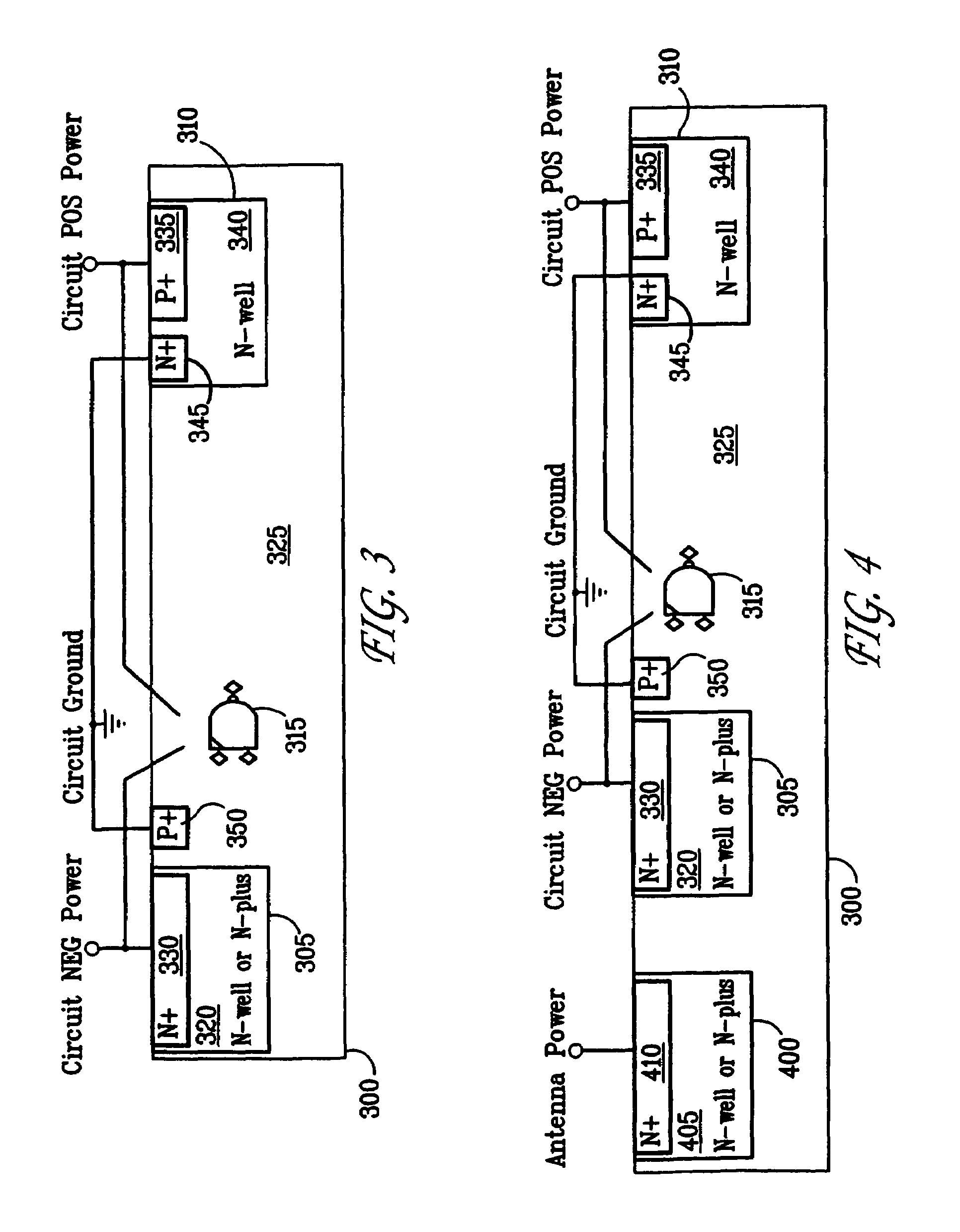
[0012]The present invention is defined by the following claims, and nothing in this section should be taken as a limitation on those claims. By way of introduction, the embodiments described below include a method and apparatus for supplying power from a light source for a transponder.

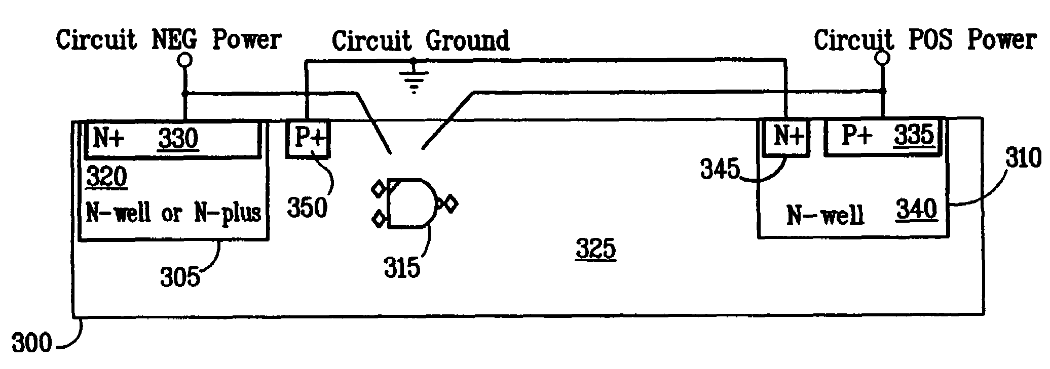
[0013]In order to minimize size and cost, it is desirable to manufacture a transponder using a standard CMOS process on a single die. Standard CMOS processes utilize a common, conductive substrate. Thus, without additional processing, any one photovoltaic element is not completely isolated from another.

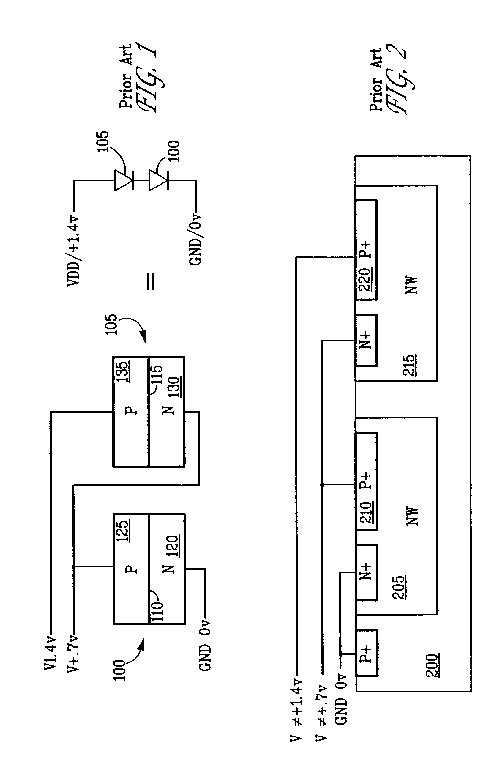
[0014]In instances where more than one photovoltaic element is used to supply sufficient power, the common substrate causes difficulties. For example, if an increased voltage differential is desired, two photodiodes may be connected in series. In processes where the two photodiodes are isolated, the series connection will double the voltage produced. If the two photodiodes are not isolated, as with the u...


PUM


Abstract

A system and method for providing power to a light-powered transponder. In order to create a sufficient voltage differential, two different photovoltaic elements are used. The photovoltaic elements generate voltages of different polarities. Because the photovoltaic elements are used independently to generate voltages with different polarities, the present system can achieve a desired voltage differential despite the inherent difficulties presented by the use of a standard CMOS process.

Description

[0001]This application is a continuation of Ser. No. 09 / 858,295 filed May 15, 2001, now abandoned.BACKGROUND OF THE INVENTION[0002]This invention relates generally to electronic radio frequency identification tags and specifically to small electronic transponders that store and transmit information. In particular, the present invention relates to the use of light to generate sufficient power for transponders.[0003]Electronic transponders are used in a wide variety of applications to store and transmit information. A transponder functions by receiving a transmission request and, in turn, transmitting a response. Typically, this response is an identification signal, often comprising a serial number.[0004]In World War II, transponders were used to identify aircraft. The transponder assured the requesting aircraft that the associated aircraft was a friendly aircraft by transmitting an identification code. Early versions of electronic transponders supplied power by way of a battery or a ...

Claims


Application Information

Patent Timeline
Patent Type & Authority Patents(United States)
IPC IPC(8): H01L31/04H01L31/05H01L27/142
CPCH01L27/142Y10S136/293Y02E10/50
Inventor ARMER, JOHNSENKO, THOMAS RICHARD
Owner PHARMASEQ INC
Why Eureka
Try Eureka