
Eureka
For R&D, Eureka makes reading and utilizing patents & technical documents easy.
Eureka AIR
Designed for self-driven R&D workflows. Generate viable solutions, solve complex R&D challenges, empower your innovation with AI.

Eureka Materials
Designed for material experts only. Revolutionize your material R&D, from search, analyze, to developing new materials.

TechResearch
Generate reliable direction feasibility study reports for your R&D in just a few steps.

TechSeek
Discover and master advanced knowledge NOW. Basics, ideas, possibilities, all at once.

TechMind
As an expert in R&D Theories, TechMind can generates customized viable solutions instantly.

TechRisk
Analyze your overall solution with one click, know your potential R&D risks in advance.

TechMonitor
Get weekly tech updates, stay abreast of the latest tech innovations and key insights.
Frequency-tunable resonator
- Summary
- Abstract
- Description
- Claims
- Application Information
AI Technical Summary
Benefits of technology
Problems solved by technology
Method used
Image

Examples
Embodiment Construction
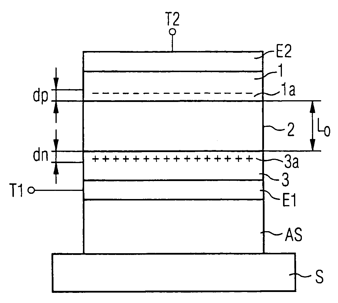
[0032]As a first exemplary embodiment, a BAW resonator is manufactured on the basis of zinc oxide (ZnO) as a piezoelectric material. Except for the manufacture of the semiconducting layers, the construction of such a resonator takes place in accordance with methods that are known in principle, from, e.g., K. M. Lakin et al., Microwave Symposium Digest, IEEE MTT-S International 1995, pp. 838 to 886.
[0033]In FIG. 1, silicone, for example, can be used as a substrate. However, other substrate materials such as glass, SiC, SiGe, InP, GaAs, sapphire, or others are also possible. In order to avoid acoustic losses in the substrate material, the resonator can be constructed as a bridge structure, an air gap being situated between the lowest electrode E1 and the substrate material S. However, it is also possible, in particular as shown in FIG. 1, to provide an acoustic mirror AS between the substrate and the lowest electrode. This can easily be produced from quarter-wave layers, for example, ...
PUM
 Abstract
Description
Claims
Application Information
 - R&D Engineer
- R&D Manager
- IP Professional
- Industry Leading Data Capabilities
- Powerful AI technology
- Patent DNA Extraction
Browse by: Latest US Patents, China's latest patents, Technical Efficacy Thesaurus, Application Domain, Technology Topic, Popular Technical Reports.
© 2024 PatSnap. All rights reserved.Legal|Privacy policy|Modern Slavery Act Transparency Statement|Sitemap|About US| Contact US: help@patsnap.com