Piezoelectric oscillator

a piezoelectric oscillator and piezoelectric technology, applied in the direction of generator/motor, solid-state device, basic electric elements, etc., can solve the problems of inability to mount ic devices and other electronic parts, inability to fully maintain the piezoelectric oscillator reliability, etc., to achieve the effect of further improving the sealing property of the ic devi

Active Publication Date: 2006-08-29
KYOCERA CORP
View PDF10 Cites 32 Cited by
  • Summary
  • Abstract
  • Description
  • Claims
  • Application Information

AI Technical Summary

Benefits of technology

[0013]In the piezoelectric oscillator, since part or all of the IC device is coated with the resin material and at least inner side faces of the metal bodies, which face the IC device, are also coated with the resin material, oxidative corrosion of the IC device and the metal bodies can be prevented effectively. This gives an advantage that a high reliability of the piezoelectric oscillator can be maintained and bonding strength between the supporting substrate and the metal bodies can be increased by using the resin material.
[0029]Especially when the mounting legs are individually attached at four corners on the surface of the supporting substrate, since the vertical section of each mounting leg is formed substantially in the shape of a trapezoid, liquid resin before hardening flows between the mounting legs and the IC device more easily. Accordingly, the sealing property of the IC device can be further improved.

Problems solved by technology

However, in the above-mentioned conventional piezoelectric oscillator, oxidization corrosion of metal bodies forming connection electrodes 24 cannot prevent and reliability of the piezoelectric oscillator cannot be fully maintained.
That is, the level difference of the recess 25 leads to an disadvantage that the IC device and other electronic parts cannot be mounted.

Method used


Image

  • Piezoelectric oscillator
  • Piezoelectric oscillator
  • Piezoelectric oscillator

Examples


Embodiment Construction

[0046]The present invention will be described in detail with reference to accompanying drawings.

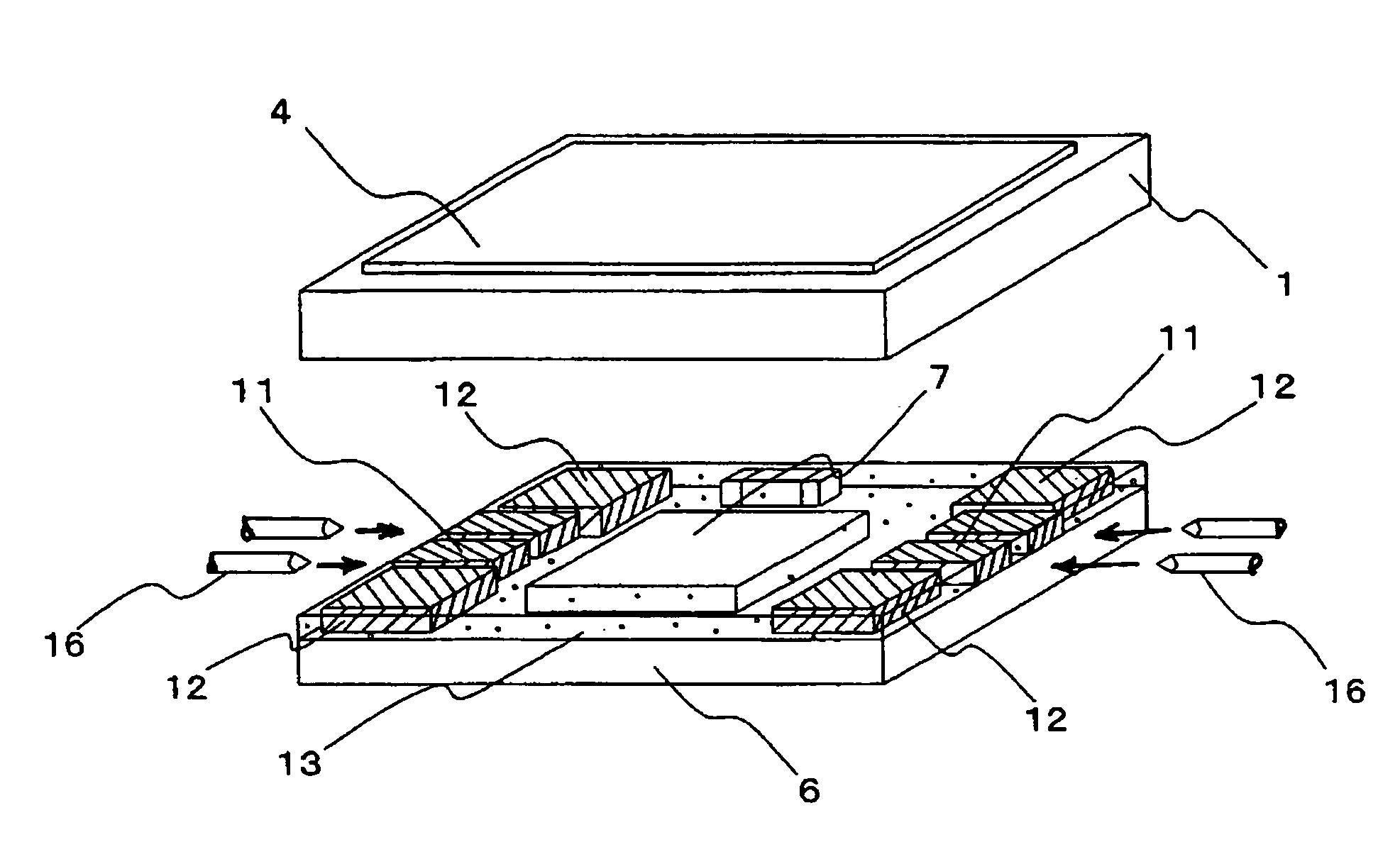
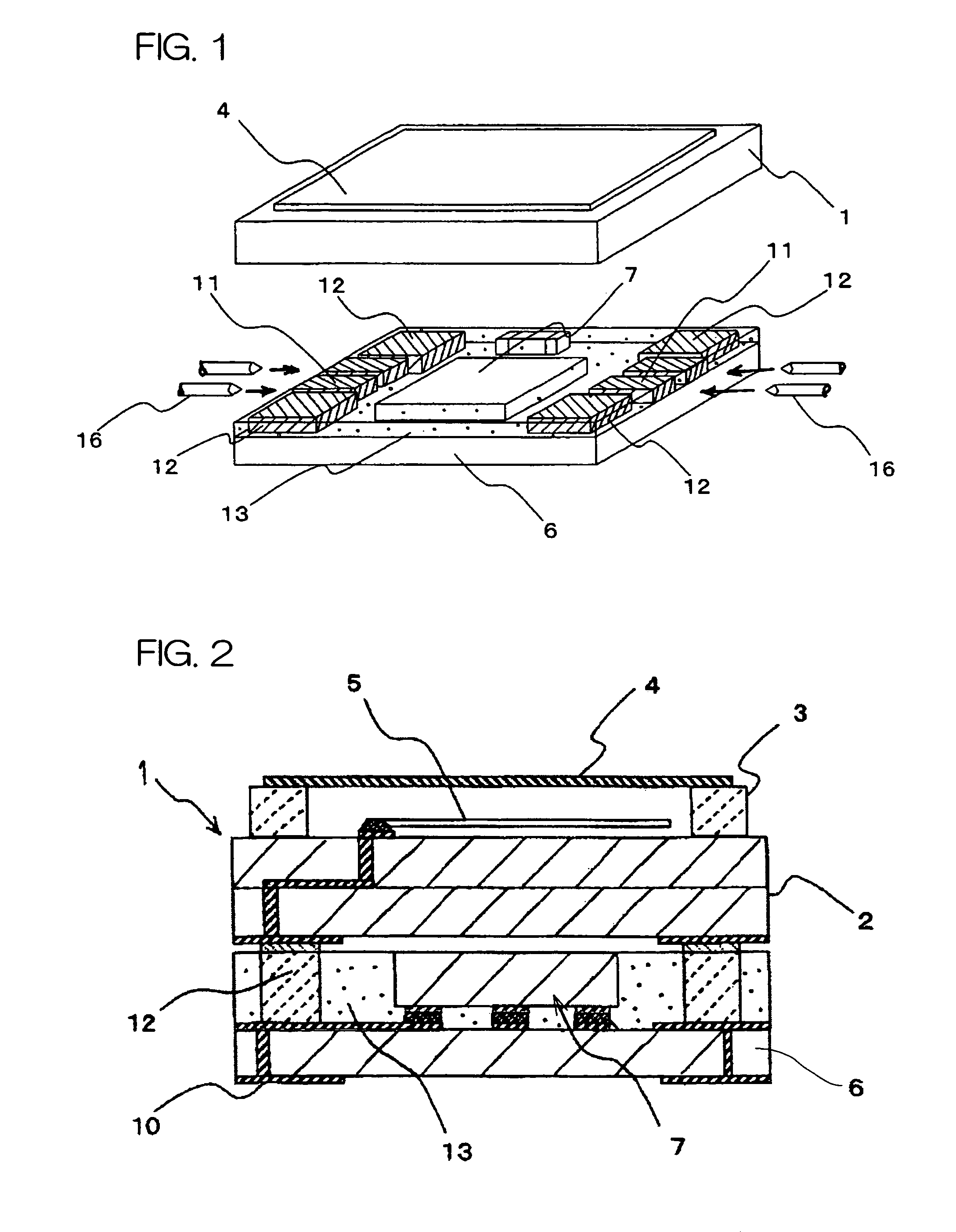
[0047]FIG. 1 is an exploded perspective view showing a temperature-compensated quartz-crystal oscillator using a piezoelectric oscillator of the present invention, and FIG. 2 is a sectional view of the temperature-compensated quartz-crystal oscillator of FIG. 1.

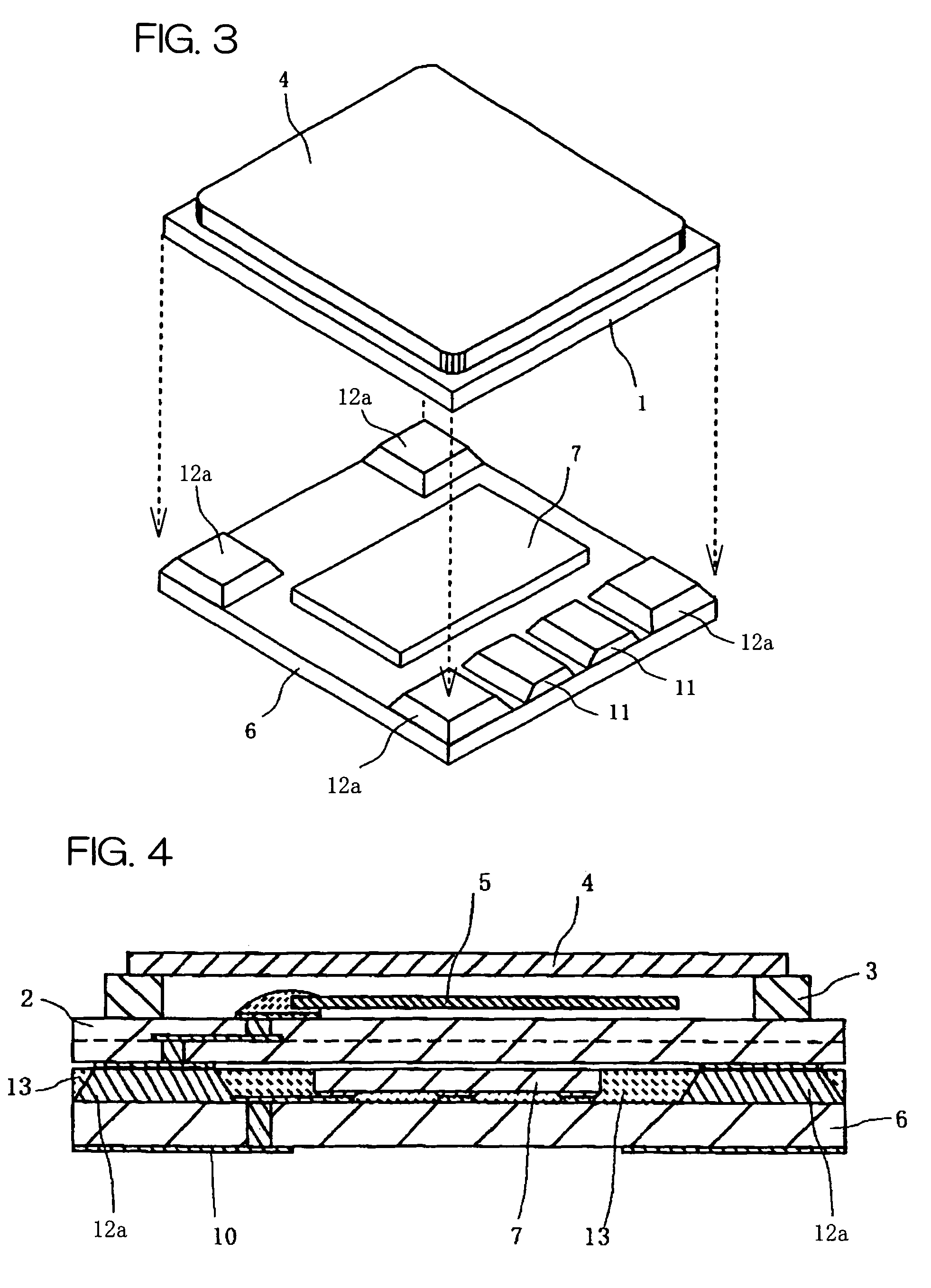
[0048]The temperature-compensated quartz-crystal oscillator shown in FIGS. 1 and 2 has a rectangular package 1 accommodating a quartz-crystal oscillation device 5 as a piezoelectric vibrator therein and a supporting substrate 6 having a plurality of external terminals 10 on a bottom face thereof and an IC device 7 on a top face thereof. The package 1 is seated on / fixed to the supporting substrate via spacer members 12. The outside dimension of the package 1 and the outside dimension of the supporting substrate 6 in every direction are substantially equal in a plan view.

[0049]The package 1 includes a substrate 2 formed from a cerami...


PUM


Abstract

A quartz-crystal oscillator has a configuration wherein a rectangular container 1 accommodating a piezoelectric oscillator device 5 therein is fixed to a rectangular supporting substrate 6 on which an IC device 7 is mounted via spacer members 12 formed of metal bodies. On the surface of the supporting substrate 6, part or all of the IC device 7 and side faces of the spacer members are coated with a resin material. When the quartz-crystal oscillator is implemented on a main board by soldering or the like, the problem that the solder for bonding the quartz-crystal oscillator to the main board is adhered to the spacer members 12, thereby causing a short-circuit can be effectively prevented.

Description

BACKGROUND OF THE INVENTION[0001]1. Field of the Invention[0002]The present invention relates to a piezoelectric oscillator used for generating a clock signal in telecommunication equipment, electronic equipment, or the like.[0003]2. Description of the Related Art[0004]Clock signal generators (timing devices) for portable communication units and the like have conventionally employed piezoelectric oscillators such as a temperature-compensated quartz-crystal oscillator.[0005]As shown in FIG. 15, for example, in the conventional temperature-compensated quartz-crystal oscillator, a package 23 accommodating a quartz-crystal oscillation device therein is attached on a supporting substrate 21 having a recess 25 in a central region on a top face thereof and a plurality of external terminals on a bottom face thereof. The known oscillator is configured so that an IC device 26 for outputting an oscillation signal on the basis of oscillation of the quartz-crystal oscillation device is accommoda...

Claims


Application Information

Patent Timeline
Patent Type & Authority Patents(United States)
IPC IPC(8): H03H9/05H01L41/053H03H9/21H03H9/215H01L23/58H02N2/00
CPCH03H9/1021H03H9/0547H01L2924/16195
Inventor SASAGAWA, RYOMAMIURA, HIROYUKI
Owner KYOCERA CORP
Why Eureka
Try Eureka