Controller in a voltage mode buck converter for implementing a mode-switch function and an over-current protection by a multifunction pin and method thereof

a multi-function pin and converter technology, applied in the field of voltage converters, can solve the problems of difficult to precisely detect overcurrent and overcurrent protection of high-side switch sensing methods by conventional methods, and achieve the effect of reducing the number of pins required for the controller

Active Publication Date: 2006-08-29
ANPEC ELECTRONICS CORPORATION
View PDF4 Cites 68 Cited by
  • Summary
  • Abstract
  • Description
  • Claims
  • Application Information

AI Technical Summary

Benefits of technology

[0007]Since the controller accomplishes the mode switch function and the over-current protection by a single pin, the number of the pins required for the controller is reduced.

Problems solved by technology

Particularly, for those applications of power conversion from high voltage to low voltage and high speed switching, sensing the current flowing through the high side switch by conventional methods has been hard to precisely detect the over current.
Owing to such short conductive period, the noise caused by inductor, capacitor and load variation would bring the over-current protection with abnormal detection.

Method used


Image

  • Controller in a voltage mode buck converter for implementing a mode-switch function and an over-current protection by a multifunction pin and method thereof
  • Controller in a voltage mode buck converter for implementing a mode-switch function and an over-current protection by a multifunction pin and method thereof
  • Controller in a voltage mode buck converter for implementing a mode-switch function and an over-current protection by a multifunction pin and method thereof

Examples


Embodiment Construction

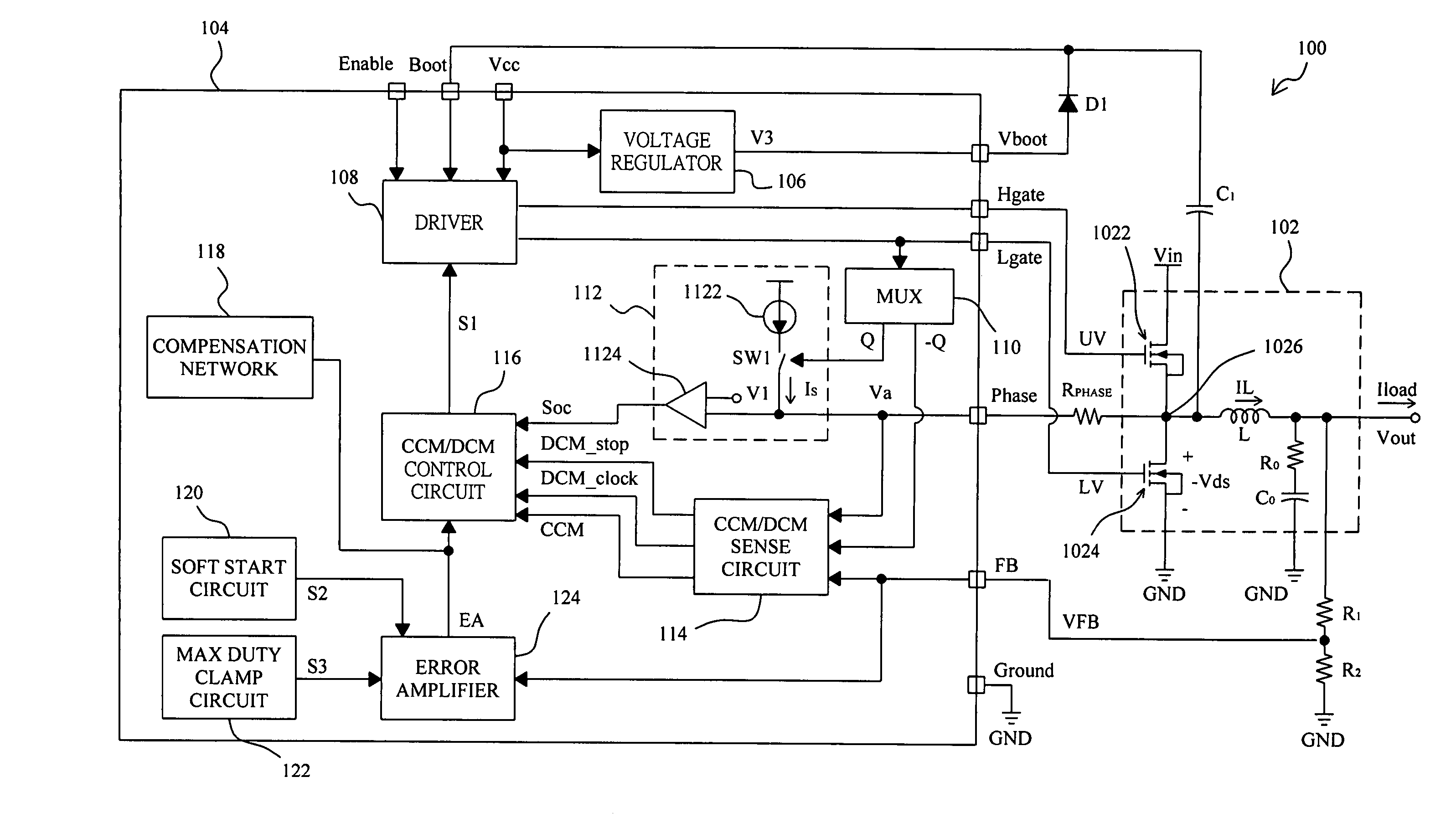
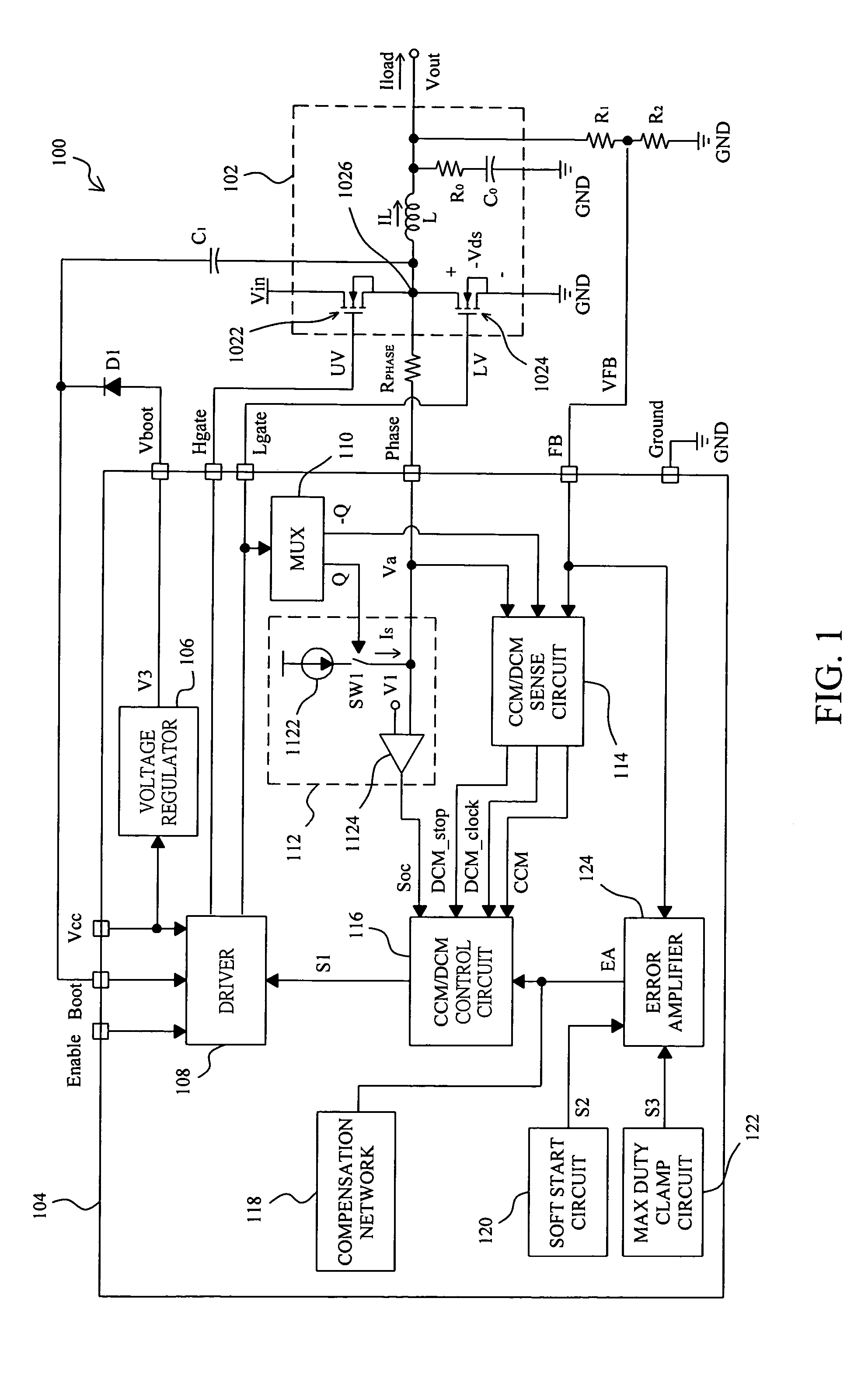
[0014]FIG. 1 shows a voltage mode buck converter 100, which comprises an output stage 102 operated by a PWM controller 104 of the present invention. The output stage 102 has a high side MOS transistor 1022 connected between an input voltage Vin and a phase node 1026, and a low side MOS transistor 1024 connected between the phase node 1026 and ground GND. The high side and low side MOS transistors 1022 and 1024 are switched by drive signals UV and LV respectively, to generate an output voltage Vout and a load current Iload. A voltage divider composed of resistors R1 and R2 is connected between the output voltage Vout and ground GND to generate a feedback voltage VFB supplied to a feedback pin FB of the controller 104.

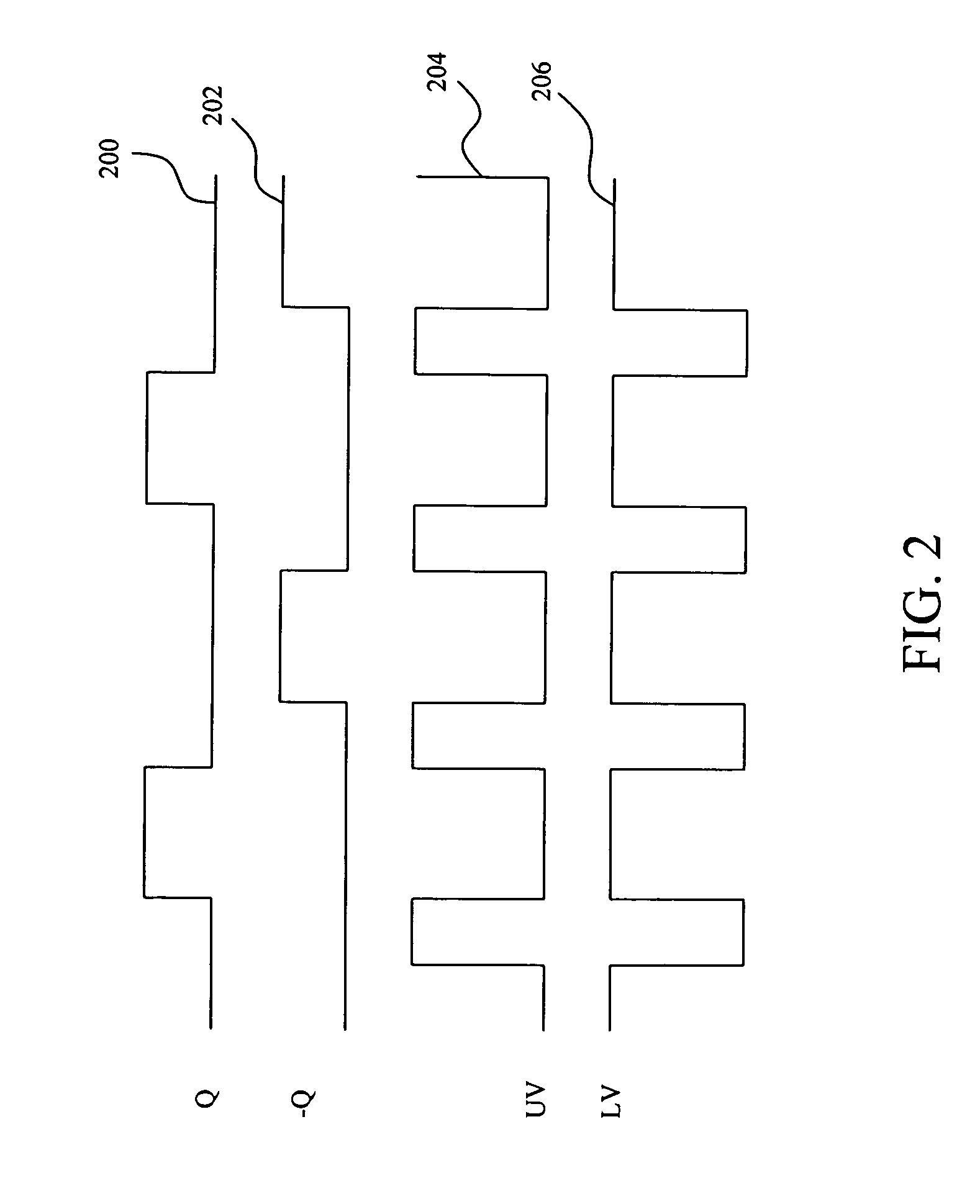
[0015]In the controller 104, a multiplexer 110 is also connected with the drive signal LV for the low side MOS transistor 1024, to divide the duties of the drive signal LV to thereby generate control signals Q and −Q for an over-current sense circuit 112 and a CCM / DCM se...


PUM


Abstract

In a voltage mode buck converter having a pair of switches connected in series by a phase node to be switched by a pair of drive signals generated from a first control signal, a phase resistor is connected between a multifunction pin and the phase node, and a controller generates a second control signal and a third control signal from the second drive signal to sense the voltage on the multifunction pin respectively to generate an over-current signal and a CCM mode switch signal to switch the converter between a CCM mode and a DCM mode.

Description

FIELD OF THE INVENTION[0001]The present invention is related generally to a voltage converter, and more particularly, to a controller in a voltage mode buck converter for implementing a mode switch function and an over-current protection by a multifunction pin.BACKGROUND OF THE INVENTION[0002]A voltage mode buck converter is used to regulate the level of a direct current (DC) voltage and maintain the regulated voltage stably at a desired level, by switching a high side switch and a low side switch to generate voltage pulses through a low-pass filter including inductor and capacitor to generate a DC output voltage. An assortment of appliances has been specified in their consumed powers under stand-by modes in an energy saving (Green Power) program driven by some advanced countries. By analyzing the power consumptions specified in stand-by modes, it was clearly found that the switching loss of the power elements such as power MOSFET in a voltage mode buck converter takes the most perc...

Claims


Application Information

Patent Timeline
Patent Type & Authority Patents(United States)
IPC IPC(8): G05F1/652G05F1/10H02H7/12H02M1/32H02M3/158
CPCH02H7/1213H02M3/158H02M1/32
Inventor CHEN, MING-HSUEHCHIEN, MING CHU
Owner ANPEC ELECTRONICS CORPORATION
Why Eureka
Try Eureka