
Centralizing the lock point of a synchronous circuit

a technology of synchronous circuit and lock point, applied in the field of synchronous circuits, can solve the problems of increasing circuit power consumption and additional hardware, and achieve the effects of centralizing the lock point, improving the tuning range and the time to establish the initial lock, and increasing the siz

Inactive Publication Date: 2006-08-29
ROUND ROCK RES LLC
View PDF12 Cites 34 Cited by
  • Summary
  • Abstract
  • Description
  • Claims
  • Application Information

AI Technical Summary

Benefits of technology

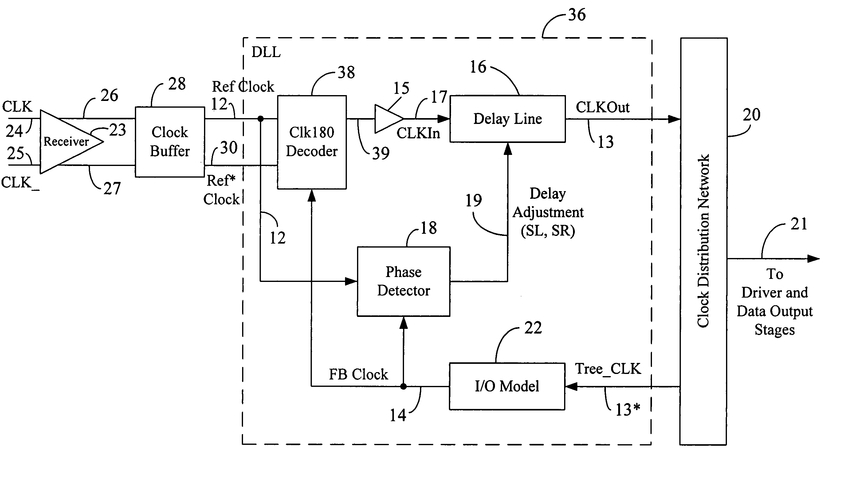
"The present patent is about a method and circuit for operating a synchronous circuit. The method involves using a delay line and a reference clock to generate a feedback clock. The feedback clock is then selectively used as an input to the delay line based on the phases of the reference clock, the inverted reference clock, and the feedback clock. This allows for better tuning and a wider range of operation in the event of changes in voltage, temperature, and frequency. The use of the inverted reference clock also improves the time to establish the initial lock and centralizes the lock point of the delay line. The circuit includes a delay line and a decoder circuit that selectively uses the reference clock and the inverted reference clock as the input clock to the delay line based on the relationship among the phases of the reference clock, the inverted reference clock, and the feedback clock. This allows for extra tuning range and improved performance without adding a delay line or changing the configuration of the existing delay line."

Problems solved by technology

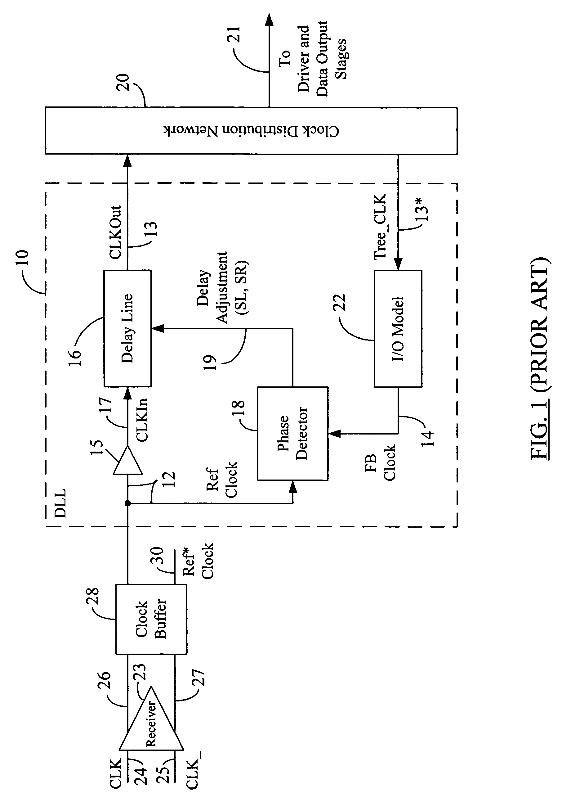
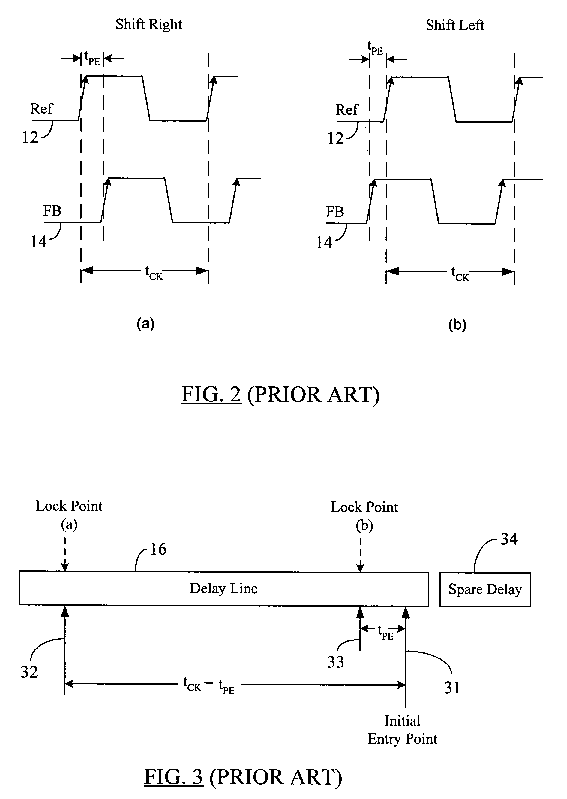
The spare delay 34 may increase circuit power consumption and may represent additional hardware.

Method used


Image

  • Centralizing the lock point of a synchronous circuit
  • Centralizing the lock point of a synchronous circuit
  • Centralizing the lock point of a synchronous circuit

Examples


Embodiment Construction

[0035]Reference will now be made in detail to some embodiments of the present disclosure, examples of which are illustrated in the accompanying drawings. It is to be understood that the figures and descriptions of the present disclosure included herein illustrate and describe elements that are of particular relevance to the present disclosure, while eliminating, for the sake of clarity, other elements found in typical solid-state memories or memory-based systems. It is noted at the outset that the terms “connected”, “connecting,”“electrically connected,” etc., are used interchangeably herein to generally refer to the condition of being electrically connected. It is further noted that various block diagrams, circuit diagrams and timing waveforms shown and discussed herein employ logic circuits that implement positive logic, i.e., a high value on a signal is treated as a logic “1” whereas a low value is treated as a logic “0.” However, any of the circuit discussed herein may be easily...


PUM


Abstract

A system and method to establish the lock point of a digital synchronous circuit (e.g., a DLL) at the center of or close to the center of its delay line is disclosed. The synchronous circuit is configured to selectively use either a reference clock or its inverted version as the clock signal input to the delay line based on a relationship among the phases of the reference clock, the inverted reference clock, and a feedback clock (generated at the output of the delay line). A delayed version of the feedback clock may be used during determination of the phase relationship. The selective use of the opposite phase of the reference clock for the input of the delay line results in centralization of the lock point for most cases as well as improvement in the tuning range and the time to establish the initial lock, without requiring an additional delay line.

Description

REFERENCE TO RELATED APPLICATION[0001]The disclosure in the present application is related to the disclosure provided in the commonly-assigned U.S. patent application Ser. No. 09 / 921,614, titled “Method to Improve the Efficiency of Synchronous Mirror Delays and Delay Locked Loops”, filed on Aug. 3, 2001.BACKGROUND[0002]1. Field of the Disclosure[0003]The present disclosure generally relates to synchronous circuits and, more particularly, to a system and method to centralize the lock point of a synchronous circuit.[0004]2. Brief Description of Related Art[0005]Most digital logic implemented on integrated circuits is clocked synchronous sequential logic. In electronic devices such as synchronous dynamic random access memory circuits (SDRAMs), microprocessors, digital signal processors, etc., the processing, storage, and retrieval of information is coordinated or synchronized with a clock signal. The speed and stability of the clock signal determines to a large extent the data rate at ...

Claims


Application Information

Patent Timeline
Patent Type & Authority Patents(United States)
IPC IPC(8): G06F1/04H03K3/00H03L7/081H03L7/10
CPCH03L7/10H03L7/0814H03L7/0816
Inventor LIN, FENG DAN
Owner ROUND ROCK RES LLC
Learn More