
Synthesis method for an active polyphase filter

a polyphase filter and polyphase synthesis technology, applied in pulse manipulation, oscillator generators, pulse techniques, etc., can solve the problems of complex bandpass transfer function, low accuracy of cut-off frequency of lowpass built with active-rc integrators if no tuning is applied, low sensitivities of these parameters to component value variation, etc., to achieve a higher level of tuning accuracy

Inactive Publication Date: 2006-08-29
WYSZYNSKI ADAM S
View PDF12 Cites 26 Cited by
  • Summary
  • Abstract
  • Description
  • Claims
  • Application Information

AI Technical Summary

Benefits of technology

[0011]The present invention is used to implement a fully-integrated continuous-time active complex IF bandpass (BP) filter denoted by numeral 67 in a wireless receiver identified by numeral 60 in FIG. 6. The receiver consists of the following components: the low-noise amplifier62, the real RF BP filter 64, the complex mixers 66, the complex IF BP filter 67 and the variable-gain amplifier 68. The present invention allows for incorporation of transmission zeros into the complex BP filter transfer function. As illustrated in FIG. 7, that yields the complex BP filter 71 with much sharper roll-off than that of an all-pole filter 72. The filter with transmission zeros 71 achieve the same attenuation of 45 dB, as illustrated by numeral 73, at 1.3 times its cutoff frequency, illustrated by the numeral 74, whereas the all-pole filter requ...

Problems solved by technology

However, since on-chip RC time-constants can vary as much as 30–40% the accuracy of cut-off frequency of a lowpass built with active-RC integrators if no tuning is applied is similarly low.
Also, since this is also an active ladder simulation method a single pole frequency and its quality (Q) factor are defined by all filter elements, which results in low sensitivities of these parameters to the component value variation.
This results in a complex bandpass transfer function.

Method used


Image

  • Synthesis method for an active polyphase filter
  • Synthesis method for an active polyphase filter
  • Synthesis method for an active polyphase filter

Examples


Embodiment Construction

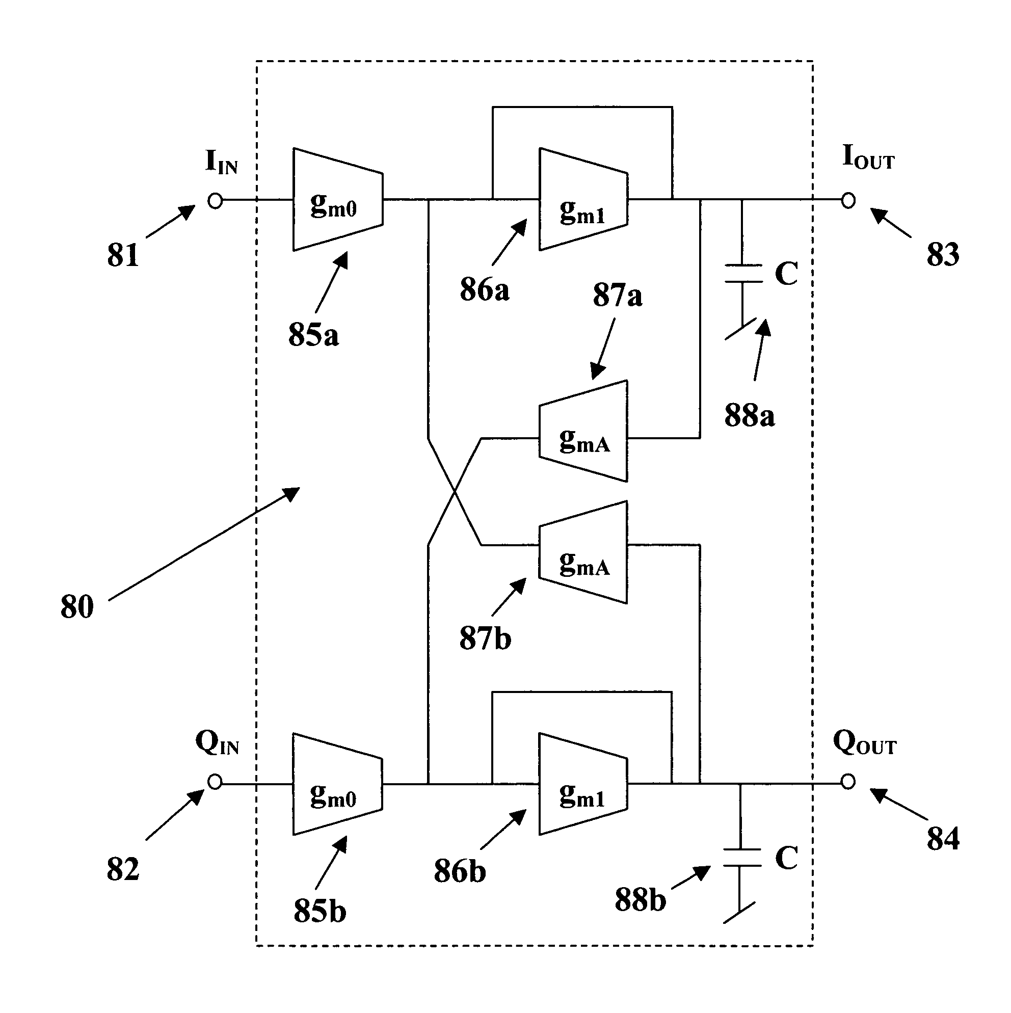
[0022]Referring to FIG. 8, a first-Order lowpass section of the present active complex all-pole bandpass filter is illustrated, and is generally identified by the numeral 80. The input signals enter the section inputs 81 and 82. The input signals are in quadrature such that if the phase of the input 81 is 0 degrees the phase of the input 82 is lagging the input 81 by 90 degrees. The input 81 is labeled I and the input 82 is labeled Q. The outputs of the filter section 80 are also in quadrature. The output 83 with phase 0 degrees is labeled I and the output 84 that is lagging output 83 by 90 degrees is labeled Q.

[0023]The lowpass section 80 realizes one complex pole and consists of six transconductors and two capacitors. The input transconductors gm0 (85a and 85b) set up the section gain. The 1 / gm1 resistors of transconductors (86a and 86b) and capacitors C (88a and 88b) form a real pole at the frequency gm1 / C that is shifted by transconductors gmA 87a and 87b in a cross-coupled conf...


PUM


Abstract

A fully-integrated continuous-time active complex bandpass IF filter that may contain transmission zeros yielding much sharper roll-off than that of an all-pole filter is implemented using transconductors and capacitors only. Each of the filter second-Order sections realizes a pair of complex poles and a may realize a double imaginary axis zero. Since the transconductors are electronically tunable the positions of filter zeros and poles are adjustable using an automatic tuning system. In each filter section the value of different transconductors are modified to separately change the pole frequency, its Q-factor and the zero frequency. Each pole and zero are separately tuned, which achieves a higher level of tuning accuracy than in case where all poles and zeros were adjusted simultaneously.

Description

TECHNICAL FIELD OF THE INVENTION[0001]The present invention relates to fully-integrated continuous-time active complex band-pass filters and their synthesis method using transconductance amplifiers and capacitors that allows direct synthesis of their transfer function poles and transmission zeros.BACKGROUND OF THE INVENTION[0002]Complex bandpass (BP) active filters are widely used in integrated receivers. These filters serve primarily as intermediate-frequency (IF) channel select filters with an additional function of providing image rejection. Their ability to reject unwanted image frequencies of the preceding mixer results directly from their non-symmetrical transfer characteristic. Depending on its input signal conditioning, a complex BP filter transmits for positive frequencies and rejects all negative frequencies, or vice-versa, the filter transmits for negative frequencies and blocks all positive frequencies.[0003]The achievable image-rejection ratio (IRR) depends on the match...

Claims


Application Information

Patent Timeline
IPC IPC(8): H03B1/00
CPCH03B27/00H03H11/22H03H2011/0494
Inventor WYSZYNSKI, ADAM S.
Owner WYSZYNSKI ADAM S
Learn More