Automatic sensitivity control for radar level gauges

a level gauge and automatic technology, applied in the direction of engine lubrication, liquid/fluent solid measurement, reradiation, etc., can solve the problem of not optimally using the dynamic range of the receiver part, the signal strength of a surface echo is reduced as a function of measured distance, and the noise level could be significantly reduced. , the effect of reducing the noise level

Active Publication Date: 2006-08-29
SAAB MARINE ELECTRONICS
View PDF13 Cites 19 Cited by
  • Summary
  • Abstract
  • Description
  • Claims
  • Application Information

AI Technical Summary

Benefits of technology

[0011]With this radar level gauge system, an automatic sensitivity control is provided. Thus, the per se known functionality of amplifying the received echo signals could now be used in a much more efficient and reliable manner, since the amplification is optimized for the actual working conditions at hand, and for the actual tank in which the system is installed. The amplification could then in a more optimized way than is heretofore known, be used, e.g. by voltage control, to provide higher amplification for echoes from larger distances, Thereby, the sensitivity of the system, and consequently also the accuracy of the measurements, is maximized by adjusting the gain based on configured tank height. The amplification increase could be fixed or be controlled based on the strength of the echoes present. Theoretically, an increase of up to 12 dB is obtainable, which would render a four times as long measuring distance possible, or a doubling of the measuring distance with half as large an antenna. This has also been confirmed in practice.
[0012]By using the present invention, echoes from a far distance have the same possibility to be recognized as nearby echoes, i.e. the amplification provides the same echo signal strength regardless of the distance, and the response could be optimized for the tank height where the system is actually used. Hereby, the dynamic range of the amplification means is more effectively used, compared to known systems where the amplification is normally dimensioned for a maximal measuring distance, e.g. 30 meters, which provides a non-optimal use of the dynamic range of the amplifier when used in tanks of other heights. Since the dynamic range of the amplification means is normally limited, it is of great importance to make as effective use of said range as possible over the measuring distance in actual use. The present invention is particularly advantageous for large measuring distances.
[0017]Preferably, the processing circuitry is arranged to amplify the echo signal before any other significant processing or manipulation of the signal. Thus, the amplifier is situated relatively close to the microwave modulation (MW) module. Hereby, the noise level could be significantly reduced.
[0018]The amplification scheme of the processing circuitry is preferably adjustable to optimize the amplification of the echo signal based on the height of the tank by means of software control, based on an input tank height value. The software could e.g. be an embedded control software, executed on an conventional signal processor as is per se known in the art By using such software control, the adjustability for different tank heights etc becomes relatively simple and cost effective, making the process of installing the radar level gauge system, and adapting the system for the working conditions at hand, relatively simple.
[0022]Further, the processing circuitry is preferably adapted to estimate information on the tank height automatically, based on at least one previously determined filling level. Hereby, the system adapts itself automatically to new conditions, whereby the installation process becomes easier and less costly. For example, a first filling level measurement could be based on a standard value, and thereafter, better estimates of the filling level could be acquired during use, based on subsequent filling level determinations. The tank height could normally be estimated to be the lowest estimated filling level, but possibly with some adjustments related to the number of filling level determinations that have been made since installation of the system or the latest reset of the system, etc.

Problems solved by technology

However, in a practical situation more than one radar echo usually can be seen and the dynamic range for the variation of all possible echoes is quite large.
However, a problem experienced in this type of level gauges is that the signal strength from a surface echo reduces as a function of measured distance.
As a consequence, the dynamic range in the receiver part is not optimally used.
Thus, many of the classical methods for increased dynamic range may not be employable.
However, a problem with these known systems is that they are relatively insensitive and static, and unable to adapt to the specific conditions related to the tank in which they are to be used, Specifically, the known systems are conventionally dimensioned for a maximal measuring distance, e.g. 30 meters.
However, in practical use the tanks are of varying height, whereby non-optimal amplification is provided.
Still further, most known systems have problems related to the noise level, due to the increased noise level generated by the amplification.
This is particularly disadvantageous in measuring systems subjected to high noise levels.

Method used


Image

  • Automatic sensitivity control for radar level gauges
  • Automatic sensitivity control for radar level gauges
  • Automatic sensitivity control for radar level gauges

Examples


Embodiment Construction

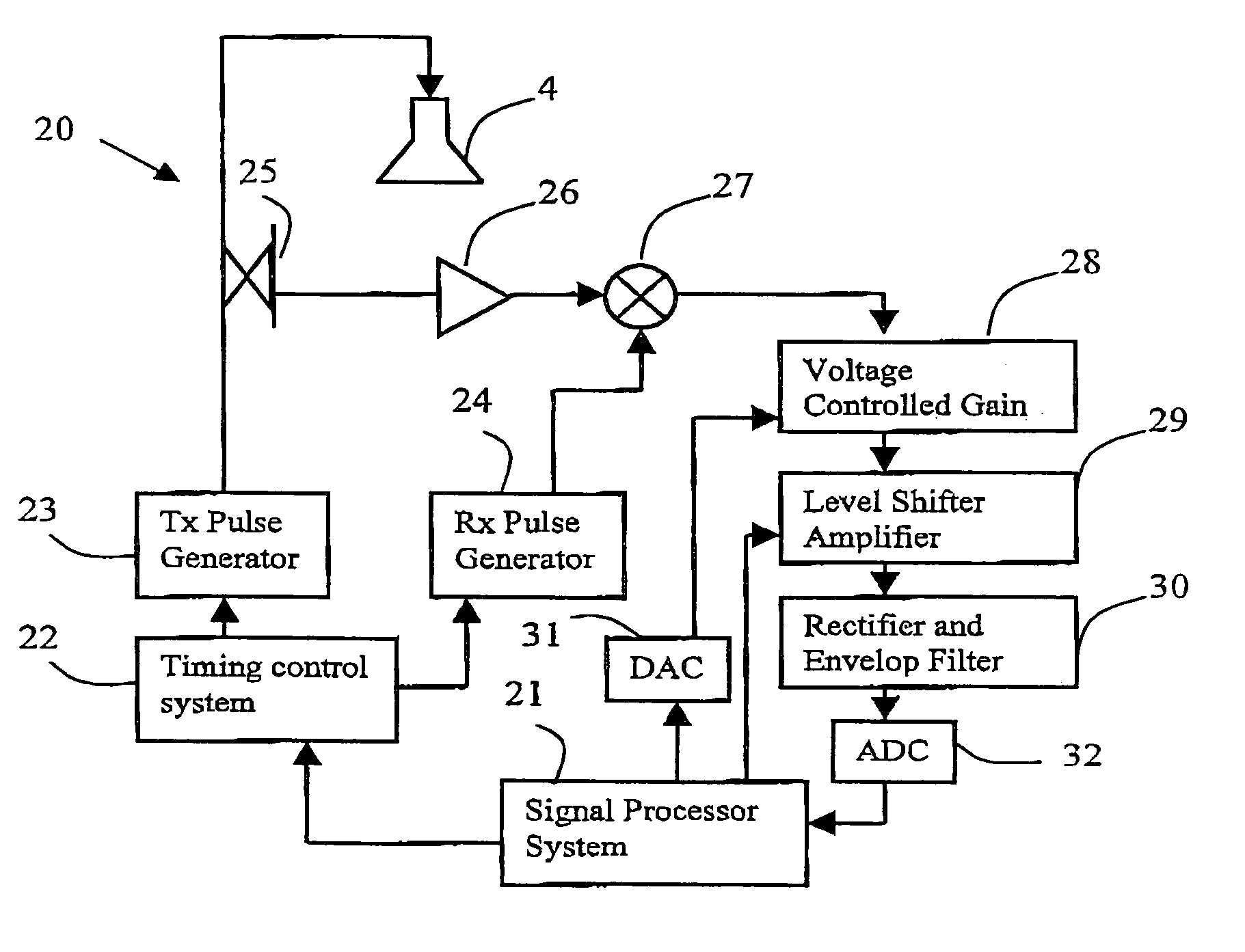
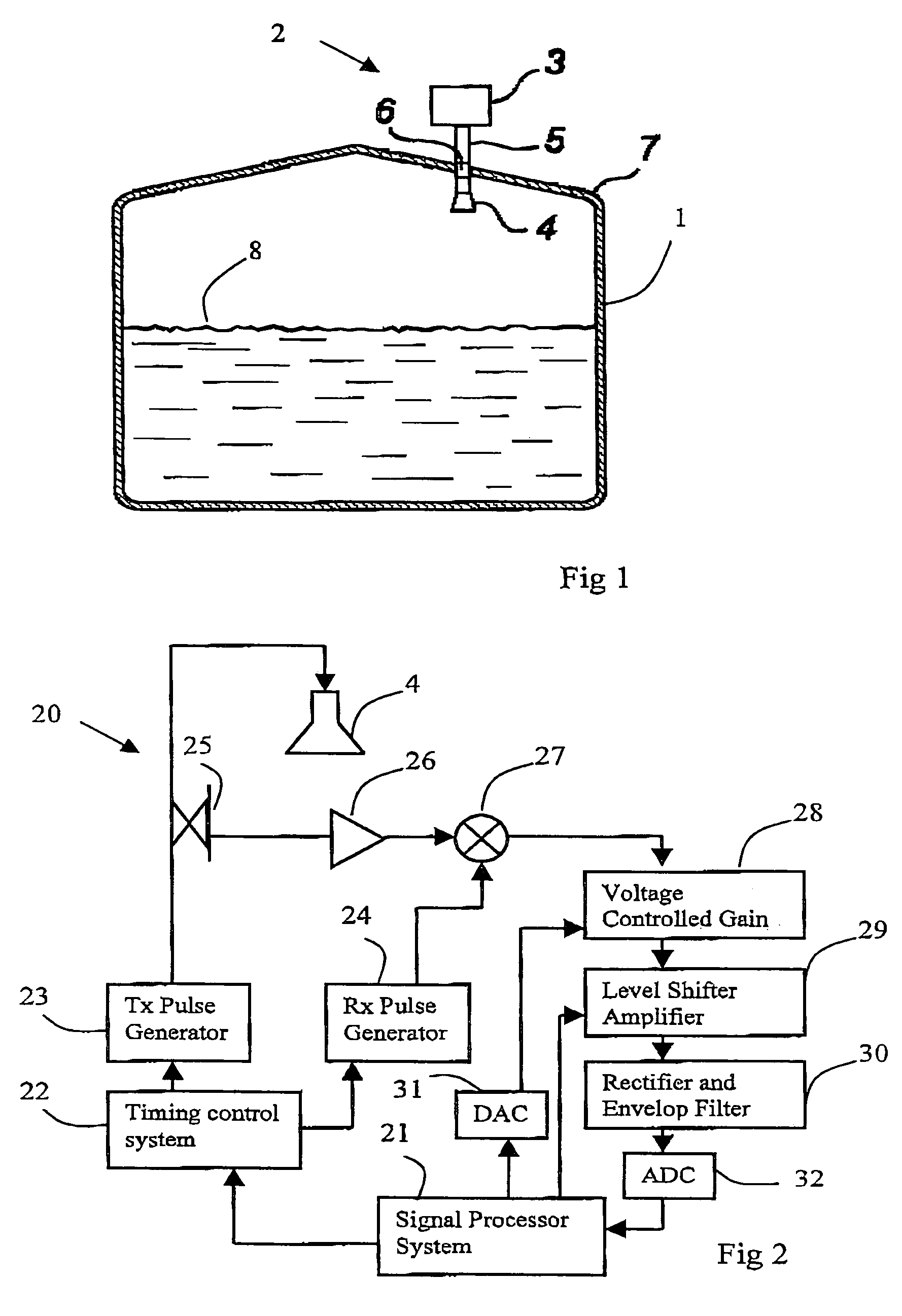
[0040]FIG. 1 shows schematically a tank 1 provided with a radar level gauge system 2. In brief, the system in FIG. 1 comprises an electronic unit 3 for transmitting and receiving radar signals and processing the received signals in order to determine the level in the tank, an antenna 4 arranged inside the tank for transmitting and receiving radar waves into the tank, and a radar wave guide assembly 5 for guiding signals between the electronic unit 3 and the antenna 4. In order to maintain temperature and pressure in the tank, and to protect the outside environment from the tank contents, a wave guide sealing 6 is arranged close to where the wave guide 5 passes through the tank wall 7 to provide sealing of the tank 1. The same antenna could preferably be used both as a transmitter for emitting the output radiation and as a receiver for receiving the reflected echo signal.

[0041]In use, the radar level gauge 2 transmits radar energy along the waveguide, 5 through the tank roof port and...


PUM


Abstract

A radar level gauge system for determining the filling level of a filling material in a tank is disclosed. The system comprises an antenna device for emitting measuring signals towards the surface of the filling material and a receiver device for receiving echo signals from the tank. Further, the system comprises processing circuitry for determining the filling level of the tank based on said echo signal, wherein said processing circuitry is adapted to amplify the received echo signals in dependence of the distance from which the echo signals originates, in such a way that an echo signal from a lower filling level is more amplified than an echo signal from a higher filling level. The processing circuitry is adjustable to optimize the amplification of the echo signal based on the height of the tank.A corresponding processing circuitry and method of operation is also disclosed.

Description

FIELD OF THE INVENTION[0001]The present invention relates to a radar level gauge system for determining the filling level of a filling material in a tank, comprising an antenna device for emitting measuring signals towards the surface of the filling material; a receiver device for receiving echo signals from the tank; and processing circuitry for determining the filling level of the tank based on said echo signal, wherein said processing circuitry is adapted to amplify the received echo signals in dependence of the distance from which the echo signals originates, in such a way that an echo signal from a lower filling level is more amplified than an echo signal from a higher filling level. Further, the invention also relates to a corresponding processing circuitry, and a method for determining the filling level of a filling material in a tank.BACKGROUND OF THE INVENTION[0002]Radar level gauges are in wide use for making non-contact measurements of the level of products such as proces...

Claims


Application Information

Patent Timeline
Patent Type & Authority Patents(United States)
IPC IPC(8): G01S13/08G01F23/284G01S7/34G01S13/88
CPCG01F23/284G01S7/34G01S13/88
Inventor ABRAHAMSSON, PAR
Owner SAAB MARINE ELECTRONICS
Why Eureka
Try Eureka