

Wet electrolytic capacitors
a technology of wet electrolytic capacitors and wet electrolytic capacitors, which is applied in the direction of electrolytic capacitors, capacitor electrodes, liquid electrolytic capacitors, etc., can solve the problems of large internal surface area of slugs and large capacitances of large wet electrolytic capacitors
- Summary
- Abstract
- Description
- Claims
- Application Information
AI Technical Summary
Benefits of technology
Problems solved by technology
Method used
Image

Examples
example 1
[0070]In this Example, experiments were performed to determine the effectiveness of NbO2 in increasing the capacitance of a cathode and producing a wet electrolytic capacitor having improved volumetric efficiency. Experiments were also performed to determine the proper sintering temperature for forming the NbO2 coated cathodes.
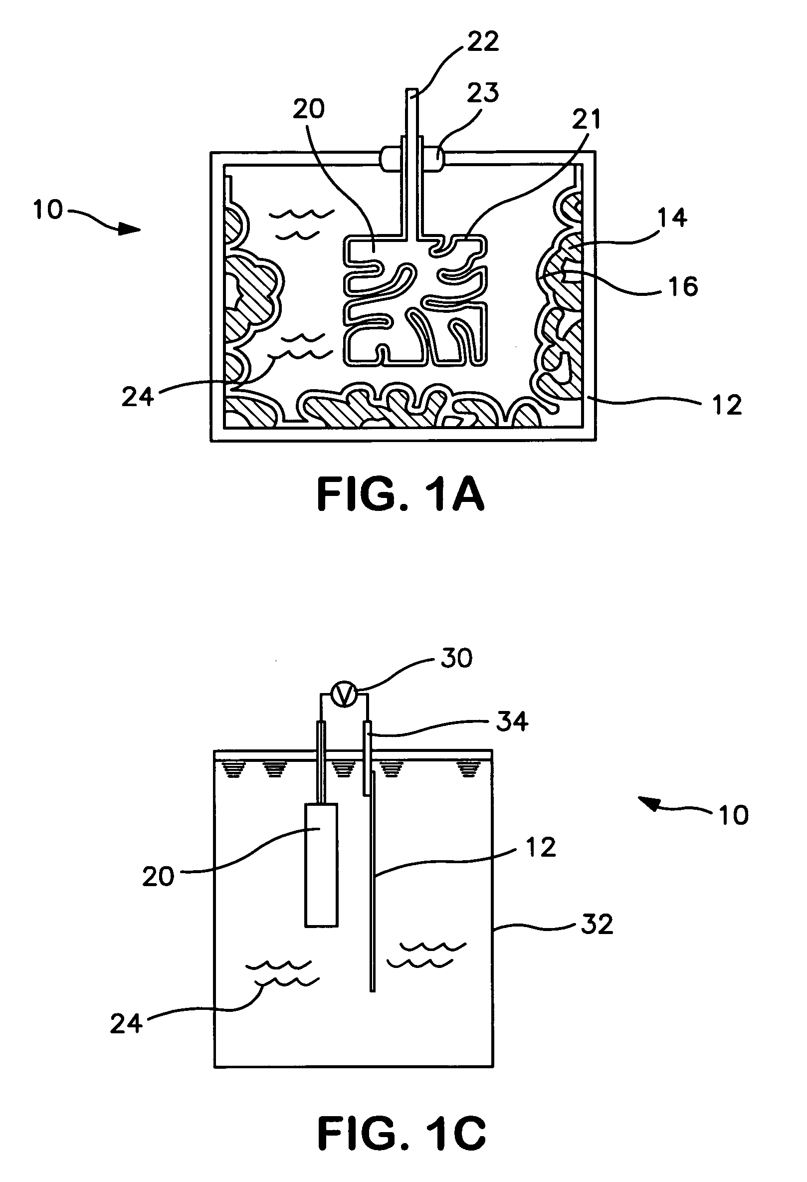
[0071]Three 1 cm2 tantalum foil units or coupons were anodized to 25 Volts to act as the anode part of a capacitor. In addition, un-anodized 1 cm2 tantalum foil coupons were coated with NbO2, on both sides, to act as the cathode part of a capacitor. The NbO2 coating procedure is outlined in detail above.
[0072]Specifically, three different NbO2 coating thicknesses were examined in this Example. Five tantalum coupons were coated with each of the three NbO2 coating thicknesses so that five different sintering temperatures could be examined. The physical dimensions and coating thicknesses of the cathode parts formed in this Example are listed below in Table 1:
[007...
example 2
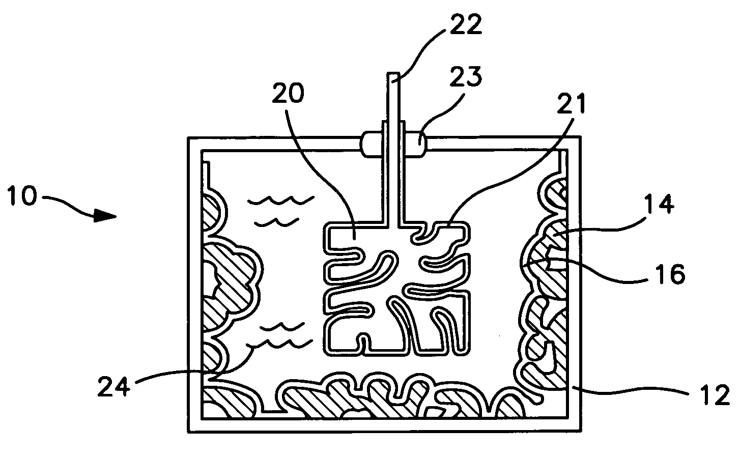
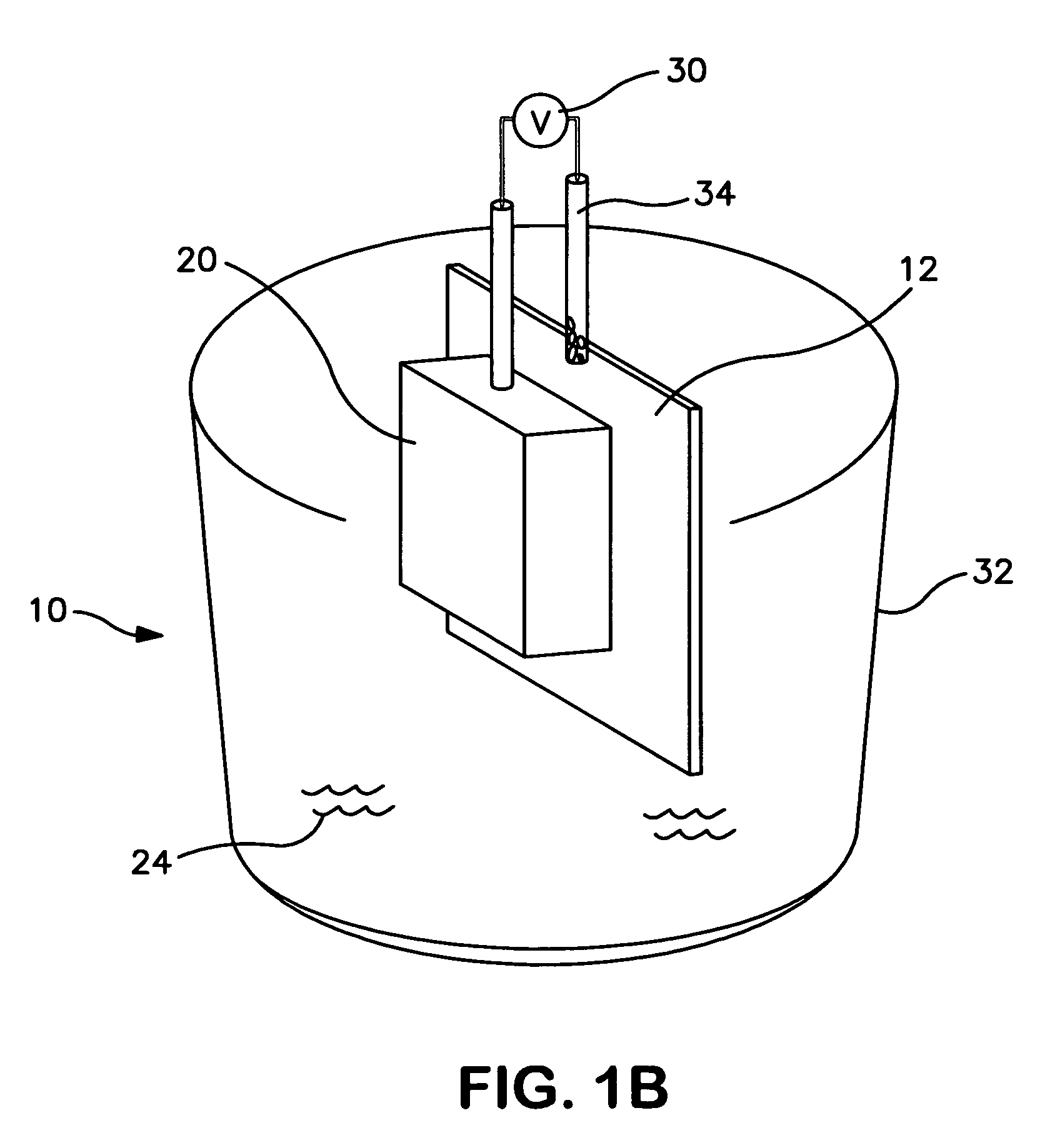
[0084]In this Example, several capacitors were formed using a Y100 tantalum anode (a nominal 100 μF tantalum anode) rather than the anodized foils used in Example 1 above. A first “control” capacitor was formed using a Y100 tantalum anode and the standard tantalum slug cathode described in Example 1 above. A second “control” capacitor was formed using a Y100 tantalum anode and the tantalum foil without any NbO2 coating described in Example 1 above. A capacitor according to the present invention was also formed using a Y100 tantalum anode and an NbO2-coated tantalum foil as the cathode. Specifically, the NbO2-coated tantalum foil used as the cathode in this capacitor was one from Group (3) of Example 1 (e.g., the cathode contained a coating comprising NbO2 having a total thickness of 23 μm) that was vacuum sintered at 1200° C. Effective capacitance and dissipation factor values for these three capacitors were obtained using the same procedure for obtaining the data recited in Table I...
example 3
[0087]In this Example, several capacitors were formed according to the present invention and were tested for their capacitance. Specifically, the cathodes in this Example were formed using tantalum coupons or foils as the metal substrate, and a coating of NbO2 was applied to each tantalum coupon or foil, followed by a coating comprising PEDT conductive polymer.
[0088]The procedure for coating the tantalum coupons with NbO2 is described in detail above, and in this Example, the amount of NbO2 used to coat the tantalum coupons was varied to determine the effects on capacitance. Thus, the NbO2-coated tantalum foil cathodes in Cathode Set 1 included 0.0056 grams of NbO2 coated on the tantalum metal; the cathodes in Cathode Set 2 included 0.0113 grams of NbO2 coated on the tantalum metal; and the cathodes in Cathode Set 3 included 0.014 grams of NbO2 coated on the tantalum metal.
[0089]Additionally, in this Example, several different amounts of PEDT were used to form conductive polymer coa...
PUM
| Property | Measurement | Unit |
|---|---|---|
| particle size | aaaaa | aaaaa |
| dissipation factor | aaaaa | aaaaa |
| particle size | aaaaa | aaaaa |
Abstract
Description
Claims
Application Information