
Apparatus for scanning optical recording media

an optical recording media and apparatus technology, applied in the field of apparatus for scanning optical recording media, can solve the problems of inability to compare the phase angle of the track error signal and the mirror signal for the purpose of direction identification, and the disadvantage of known apparatuses, so as to increase the reliability of the determination facilitate reliable identification, and increase the reliability of the intermediate track signal.

Inactive Publication Date: 2006-08-29
DEUTSCHE THOMSON-BRANDT GMBH
View PDF22 Cites 10 Cited by
  • Summary
  • Abstract
  • Description
  • Claims
  • Application Information

AI Technical Summary

Benefits of technology

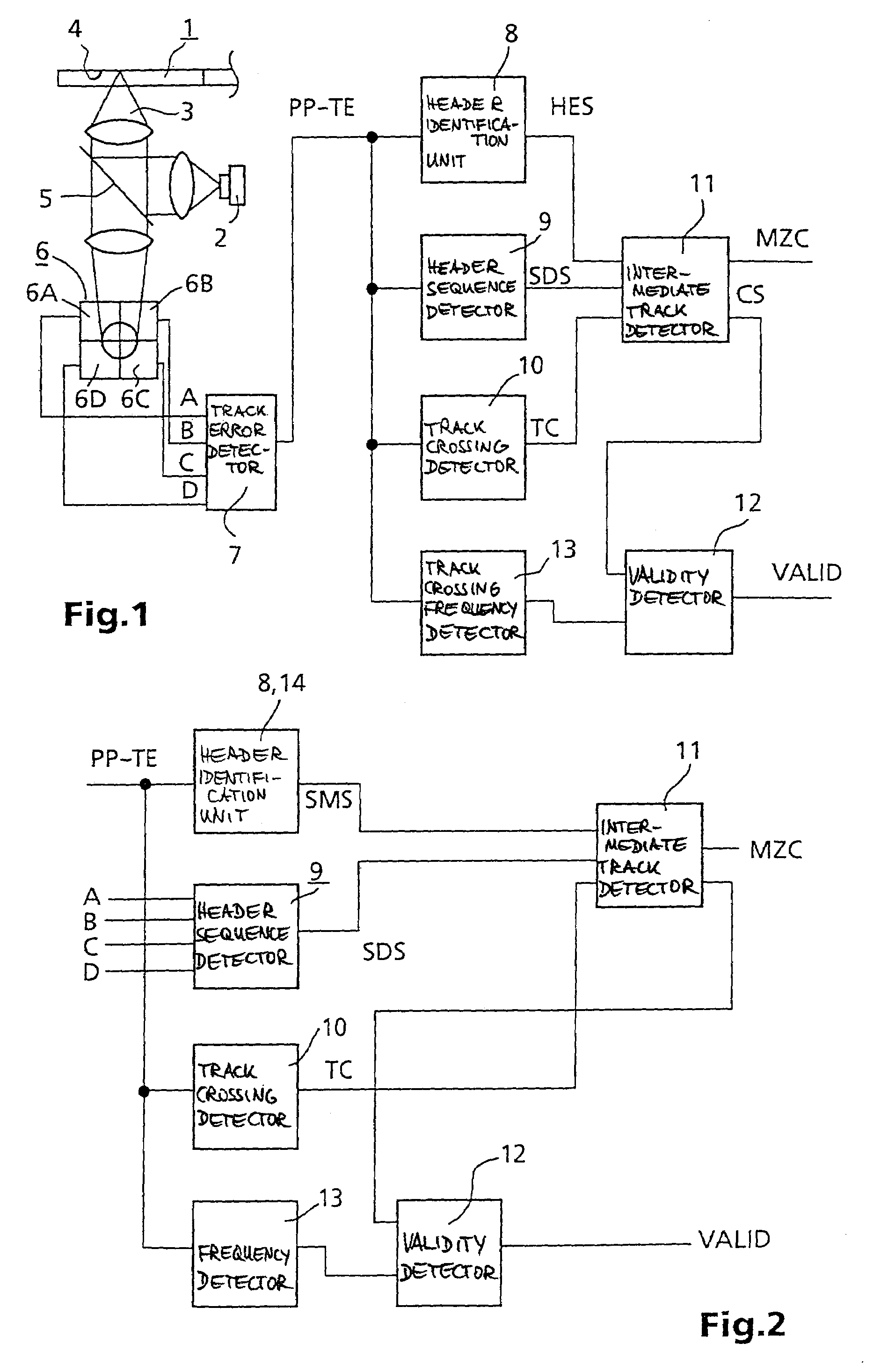
[0004]This object is achieved by virtue of the fact that the apparatus has a header sequence detector, a track crossing detector and an intermediate track detector, which is connected to outputs of the header identification unit, of the track crossing detector and of the header sequence detector, and generates an intermediate track signal. This has the advantage that an intermediate track signal is generated, thereby enabling reliable direction identification in the course of track crossing. A further advantage is that the intermediate track signal can be used to ascertain whether the track crossing operation will end on a track or on an intermediate track. Settings of the apparatus, for example parameters for the regulating circuits required for tracking, can thus be set to the expected track or intermediate track. This is advantageous particularly for recording media in which a changeover is frequently made between track and intermediate track without an offset.
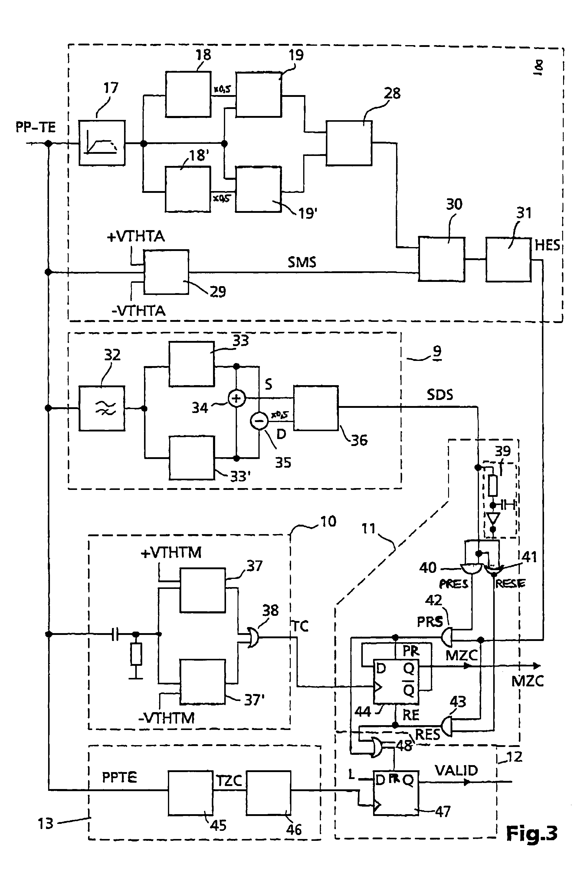
[0006]The invention furthermore provides for the header identification unit to have a high-frequency path, a low-frequency path and a signal detector, and to have a track error signal applied to it. This has the advantage of enabling reliable identification of the header areas. The track error signal contains information both about the track position and about the order, the sequence of header areas passed. The presence of the components originating from header areas in the track error signal is checked by means of the high-frequency path, and the reliability is checked in the low-frequency path. The closer to the track centre the scanning beam is, the more reliable the header identification is. From the signals of the two paths, the signal detector generates a header identification signal.
[0007]According to the invention, the header sequence detector has envelope detectors, to which a high-frequency component of a track error signal is fed, and whose outputs are connected to a comparator. This has the advantage that the order of the header markings which are arranged offset can be detected in a simple manner. Header markings leave behind high-frequency modulations in the track error signal, whose envelope is advantageously utilized for detecting the order.
[0008]In an advantageous manner, the header sequence detector has a phase detector, which is fed signals derived from detector elements of a multi-zone detector of the apparatus. This has the advantage that the header sequence determination is effected independently of the track error signal, that is to say interfering influences that may be present in the track error signal are not used for evaluation purposes. This increases the reliability of the intermediate track signal formed. The photodetector used is advantageously a photodetector that is already present in the apparatus, for example a photodetector which can be used for tracking in accordance with the differential phase detection method during the reading of recording media which are correspondingly suitable therefor.
[0009]The track crossing detector advantageously has a track error signal applied to it, and has a phase shifter or a peak value detector. This has the advantage that the track crossing detector outputs a pulse or a corresponding signal in or near the maxima and minima of the track error signal.
[0011]A development of the method according to the invention provides for the track crossing frequency to be detected, and, if a limit value is undershot, an invalidity signal to be generated, which is cancelled only when signal components which are typical of header areas are present once again. This has the advantage of increasing the reliability of the determination of the intermediate track signal. The invalidity signal indicates that conditions under which the updated intermediate track signal may be erroneous are present. This signal serves, for example, to ensure that the conclusions which can be correspondingly derived from the intermediate track signal, such as the direction information for example, are not utilized, or are utilized only with reservations, in this case.

Problems solved by technology

The known apparatus may be regarded as having the disadvantage that it is not possible, during the traversal of the tracks in the radial direction during the use of such recording media, to obtain information about the direction in which the light beam traverses the tracks of the recording medium.
Consequently, a comparison of the phase angle of the track error signal and of the mirror signal for the purpose of direction identification is no longer meaningful, on account of the doubled frequency of the mirror signal.

Method used


Image

  • Apparatus for scanning optical recording media
  • Apparatus for scanning optical recording media
  • Apparatus for scanning optical recording media

Examples


Embodiment Construction

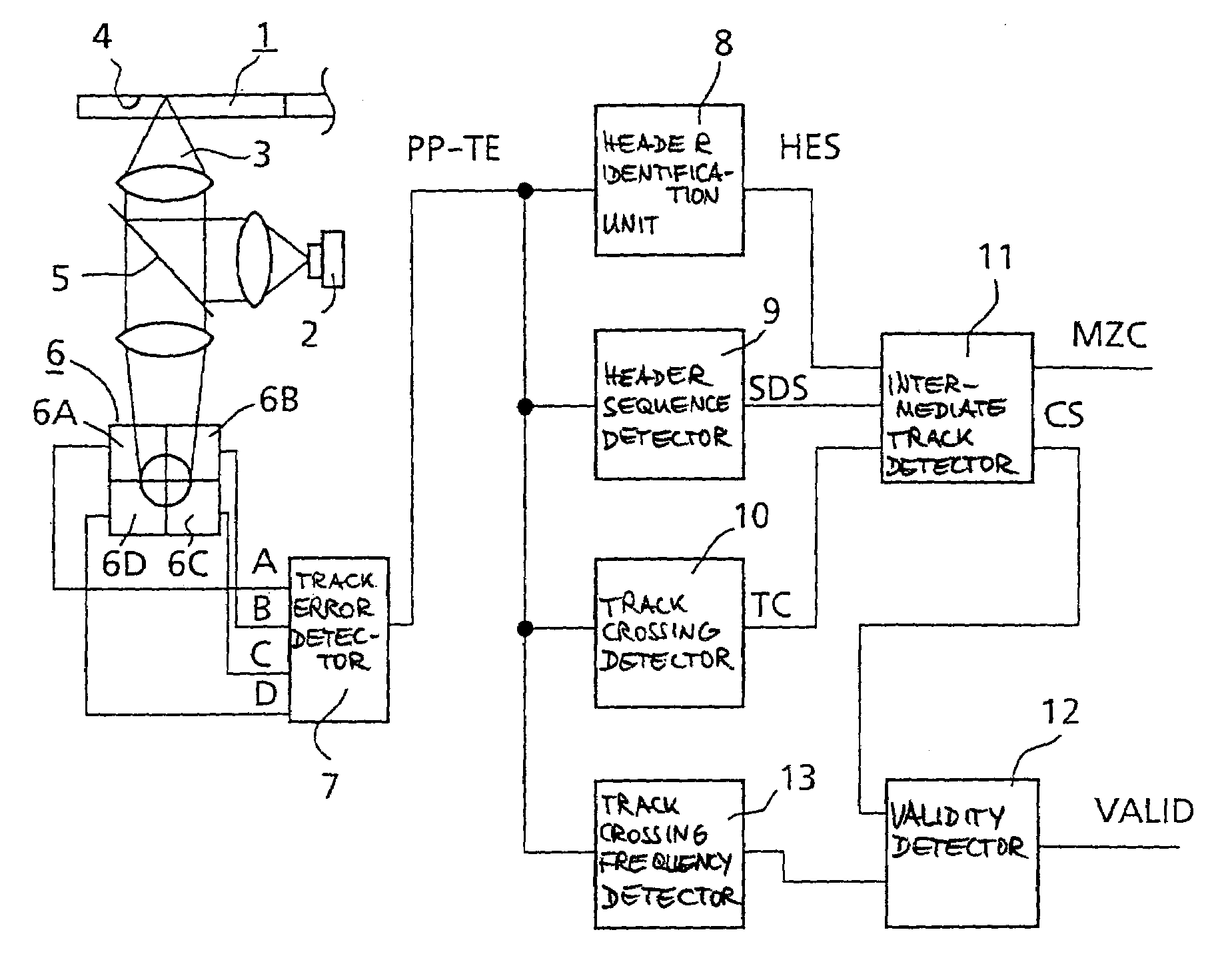
[0023]FIG. 1 shows a schematic illustration of an apparatus according to the invention. A recording medium 1, which is illustrated in section, is scanned by means of a light beam 3 generated by a light source 2. In this case, the light beam 3 is focused onto an information-carrying layer 4 of the recording medium 1. The light beam 3 is reflected from the information-carrying layer 4, passes through a semi-transparent mirror 5 and arrives at a multi-zone detector 6. The latter has four detector elements 6A, 6B, 6C, 6D in the exemplary embodiment. The detector signals A, B, C, D output by the detector elements are fed to a track error detector 7, which outputs a track error signal PP-TE. The track error signal PP-TE is fed to a header identification unit 8, which outputs a header identification signal HES when a header area is present. The track error signal PP-TE is furthermore fed to a header sequence detector 9, which outputs a sequence detector signal SDS. The track error signal P...


PUM


Abstract

An apparatus for reading and / or writing data markings of an optical recording medium having data markings arranged along a track and header markings arranged laterally offset with respect to the center of the track, the apparatus having a header identification unit. According to the present invention an intermediate track signal is formed, which enables direction identification during the traversal of tracks. The present invention comprises an apparatus having a header sequence detector, a track crossing detector and an intermediate track detector, wherein the intermediate track detector is connected to outputs of the header identification unit, the track crossing detector and the header sequence detector, and generates an intermediate track signal.

Description

FIELD OF THE INVENTION[0001]The present invention relates to an apparatus for reading data markings from and / or writing data markings to an optical recording medium, the recording medium having or being provided for having data markings arranged along a track and header markings arranged laterally offset with respect to the centre of this track, and the apparatus having a header identification unit. The order in which the header markings are offset from the centre of the track indicates, in recording media of this type, whether a track or an intermediate track follows the currently detected header area.BACKGROUND OF THE INVENTION[0002]An apparatus of this type is disclosed in EP-A2-0 801 382. This apparatus is suitable for the use of optical recording media having data markings both in the track and in the intermediate track, so-called land and groove recording media. The known apparatus may be regarded as having the disadvantage that it is not possible, during the traversal of the ...

Claims


Application Information

Patent Timeline
IPC IPC(8): G11B7/085G11B7/00G11B7/007G11B7/09
CPCG11B7/00718G11B7/08541G11B7/08505G11B7/00
Inventor BUCHLER, CHRISTIANDIETRICH, CHRISTOPH
Owner DEUTSCHE THOMSON-BRANDT GMBH
Learn More