Base station search method and mobile terminal apparatus
a mobile terminal and base station technology, applied in multiplex communication, wireless commuication services, and assessing restrictions, etc., can solve the problems of inability to receive radio waves from base stations, inability to make further communications, and inability to receive radio waves, so as to improve the communicability of mobile terminals, improve the communication environment, and high reliability
- Summary
- Abstract
- Description
- Claims
- Application Information
AI Technical Summary
Benefits of technology
Problems solved by technology
Method used
Image
Examples
embodiment 1
(Embodiment 1)
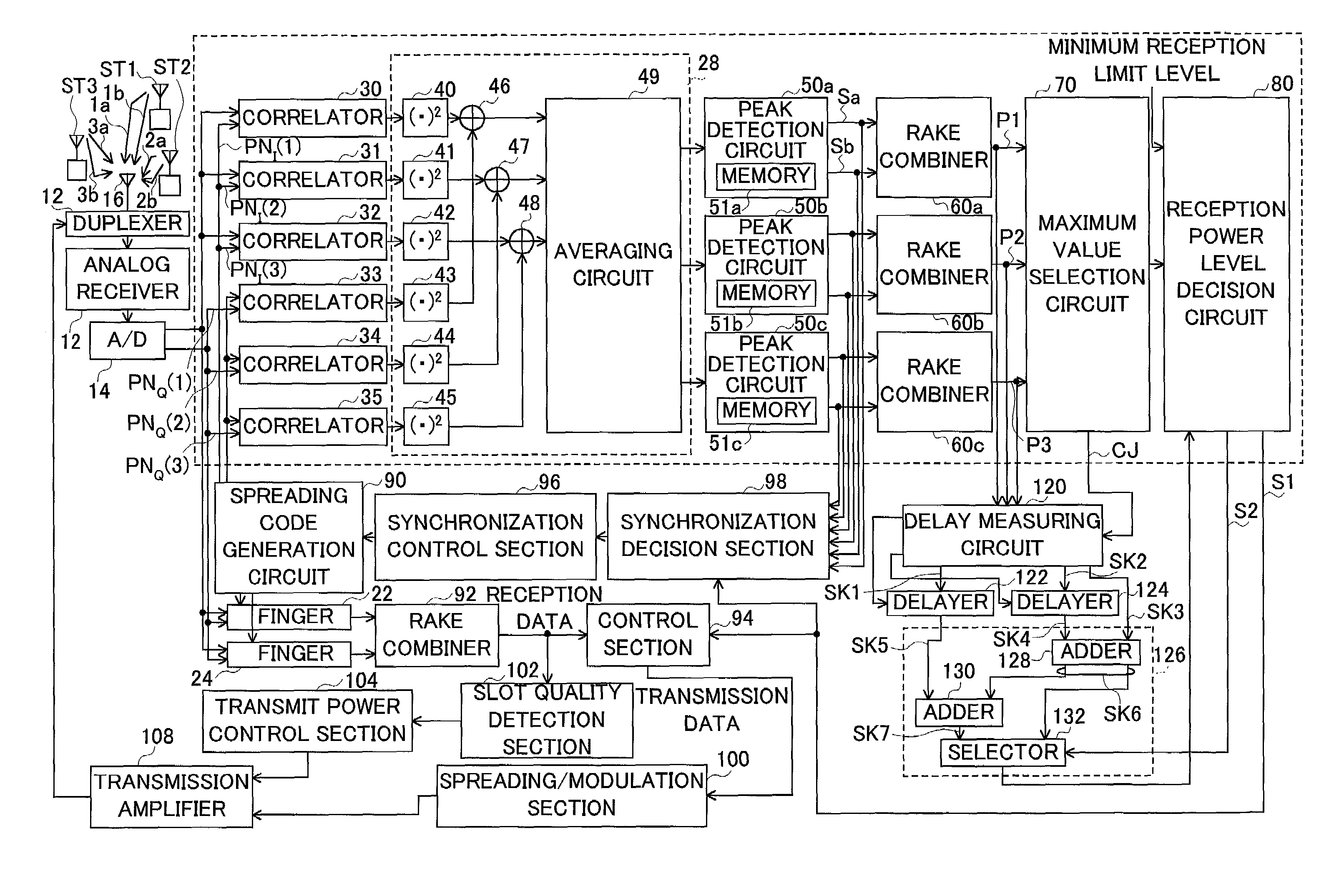
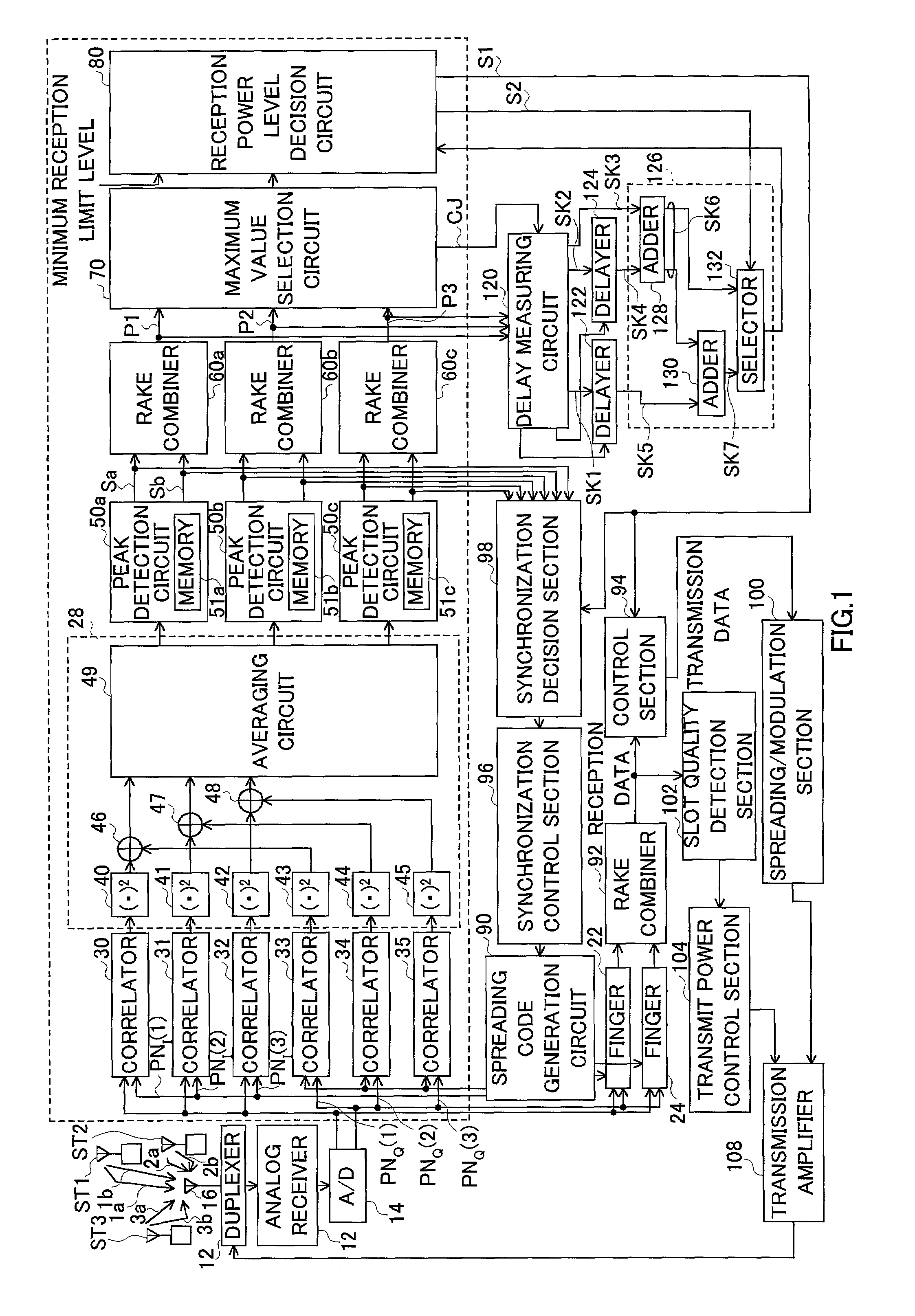
[0093]FIG. 1 is a block diagram showing a configuration of main components of a mobile radio terminal apparatus of an embodiment of the present invention.
[0094]Suppose the mobile radio terminal apparatus in FIG. 1 is in an environment in which it is possible to receive signals sent from three base stations ST1 to ST3.
[0095]Signals from the respective base stations arrive at antenna 16 of the mobile radio terminal apparatus through different paths in a multi-path environment.
[0096]Here, for convenience of explanation, suppose a signal sent by base station ST1 arrives through paths 1a and 1b, a signal sent by base station ST2 arrives through paths 2a and 2b, and a signal sent by base station ST3 arrives through paths 3a and 3b.
[0097]A signal received by antenna 16 reaches analog receiver 12 through duplexer 10 where the signal is subjected to processing of frequency conversion and converted to a digital signal by A / D converter 14.
[0098]A / D converter 14 outputs two signa...
embodiment 2
(Embodiment 2)
[0160]Of the configuration shown in FIG. 1, this embodiment will describe specific examples of circuit configurations of the delay measuring circuit, delay circuit and reception power level decision circuit.
[0161]FIG. 5 is a circuit diagram showing specific configurations of delay measuring circuit 120, delay circuit 122 or 124.
[0162]As shown in the figure, delay measuring circuit 120 is constructed of distributor 150, counter start circuit (D type flip flop) 152, counter stop circuit (D type flip flop) 154 and counter circuit 156.
[0163]Distributor 150 selects a received signal with a maximum power level out of received signals P1 to P3 based on information indicating the result of a comparison of the power levels of received signals P1, P2 and P3 from the respective base stations and outputs from output terminal a.
[0164]Furthermore, the received signal with the next highest power level (this is the received signal to be added) is output from output terminal b.
[0165]Co...
PUM
 Abstract
Description
Claims
Application Information
 - R&D
- Intellectual Property
- Life Sciences
- Materials
- Tech Scout
- Unparalleled Data Quality
- Higher Quality Content
- 60% Fewer Hallucinations
Browse by: Latest US Patents, China's latest patents, Technical Efficacy Thesaurus, Application Domain, Technology Topic, Popular Technical Reports.
© 2025 PatSnap. All rights reserved.Legal|Privacy policy|Modern Slavery Act Transparency Statement|Sitemap|About US| Contact US: help@patsnap.com


