Device for determining the exhaust gas recirculation rate of an internal combustion engine

a technology for internal combustion engines and exhaust gas, which is applied in the direction of electric control, combustion-air/fuel-air treatment, instruments, etc., can solve the problems of planar sensor failure, conventional planar sensors embedded in gas tight manners in suitable holders, etc., to detect changes in gas concentrations significantly faster, avoid crack formation, and high mechanical stability

Inactive Publication Date: 2006-09-05
DAIMLER AG
View PDF11 Cites 6 Cited by
  • Summary
  • Abstract
  • Description
  • Claims
  • Application Information

AI Technical Summary

Benefits of technology

[0011]The present invention utilizes a sensor unit which is of tubular design to make it possible, in a structurally simple way, to position the sensor-sensitive regions of the sensor unit at a distance from wall regions of respective flow lines. This is done so that the sensor-sensitive regions may be arranged at locations where the through-flow quantities are greater. In this way, it is possible to detect changes in the gas concentrations significantly more quickly compared to conventional solutions. Furthermore, the present invention's sensor units of tubular design have a high mechanical stability. It has been found that the conventional planar sensors which were embedded in a gas tight manner in a suitable holder are not as mechanically stable. For example, in operation, under cyclical thermal loads, planar sensors were exposed to high mechanical loads caused by different coefficients of thermal expansion of holder and sensor material, the mechanical stresses caused as a result, may cause the planar sensor to fail as a result of cracks forming. With the EGR sensor unit of tubular design in accordance with the present invention, it is possible to substantially avoid the formation of cracks as a result of cyclical thermal load changes. Furthermore, there is no need for complex seals with a sensor unit designed in the form of a tube.
[0012]It has been found preferable for the sensor unit of the present invention to have electrodes formed by thin-film or thick-film technology on the inner side and / or the outer side. By way of example, if a sensor thin film is deposited on a porous carrier substrate, it is possible to keep production costs very low. By way of further example, mention may be made of what is known as the dip coating process from a sol. This process is a wet-chemical process for producing ceramic thin films that is very inexpensive to implement. Furthermore, mention should be made of EVD (electrochemical vapor deposition) processes, and PVD (plasma vapor deposition) processes.
[0013]It is preferable to provide for the sensor unit to be arranged substantially centrally in the intake line, in particular an induction manifold. This measure allows the sensor-sensitive regions of the sensor unit to be positioned in a simple way, away from the wall regions of the intake line, at locations where the quantities of gas flowing through are greatest, so that very accurate measurements are possible.
[0014]According to a preferred embodiment of the device according to the invention, a sensor-sensitive region of the sensor unit formed on the outer side has a greater extent in the direction of flow of at least one of the atmospheres which are to act on the sensor unit than a sensor-sensitive region formed on the inner side. This measure can be realised, for example, by a cylindrical sensor unit in which the sensor-sensitive region formed on the outer side has a greater axial length than the sensor-sensitive region formed on the inner side. This makes it possible to effectively avoid influencing a sensor-active material on the inner side as a result of a return flow of an atmosphere acting on the outer side of the sensor unit.
[0015]It has proven expedient for the sensor unit to be designed with an NO-selective membrane on the inner side and / or the outer side. A sensor-sensitive material of this type has proven to be available at relatively low cost and allows accurate measurement to be carried out in a simple way.
[0016]Finally, it is preferable for a baffle plate to be arranged in the region of the location where the exhaust gas recirculation line opens out into the intake line. A plate of this type, on which the exhaust gas flowing into the intake line impinges, makes it possible to achieve particularly thorough mixing of exhaust gas and fresh air. It is expedient for the exhaust gas flowing into the intake line initially to flow in the opposite direction to the direction of flow of the fresh air and in the process to strike the baffle plate.

Problems solved by technology

It has been found that the conventional planar sensors which were embedded in a gas tight manner in a suitable holder are not as mechanically stable.
For example, in operation, under cyclical thermal loads, planar sensors were exposed to high mechanical loads caused by different coefficients of thermal expansion of holder and sensor material, the mechanical stresses caused as a result, may cause the planar sensor to fail as a result of cracks forming.

Method used


Image

  • Device for determining the exhaust gas recirculation rate of an internal combustion engine
  • Device for determining the exhaust gas recirculation rate of an internal combustion engine

Examples


Embodiment Construction

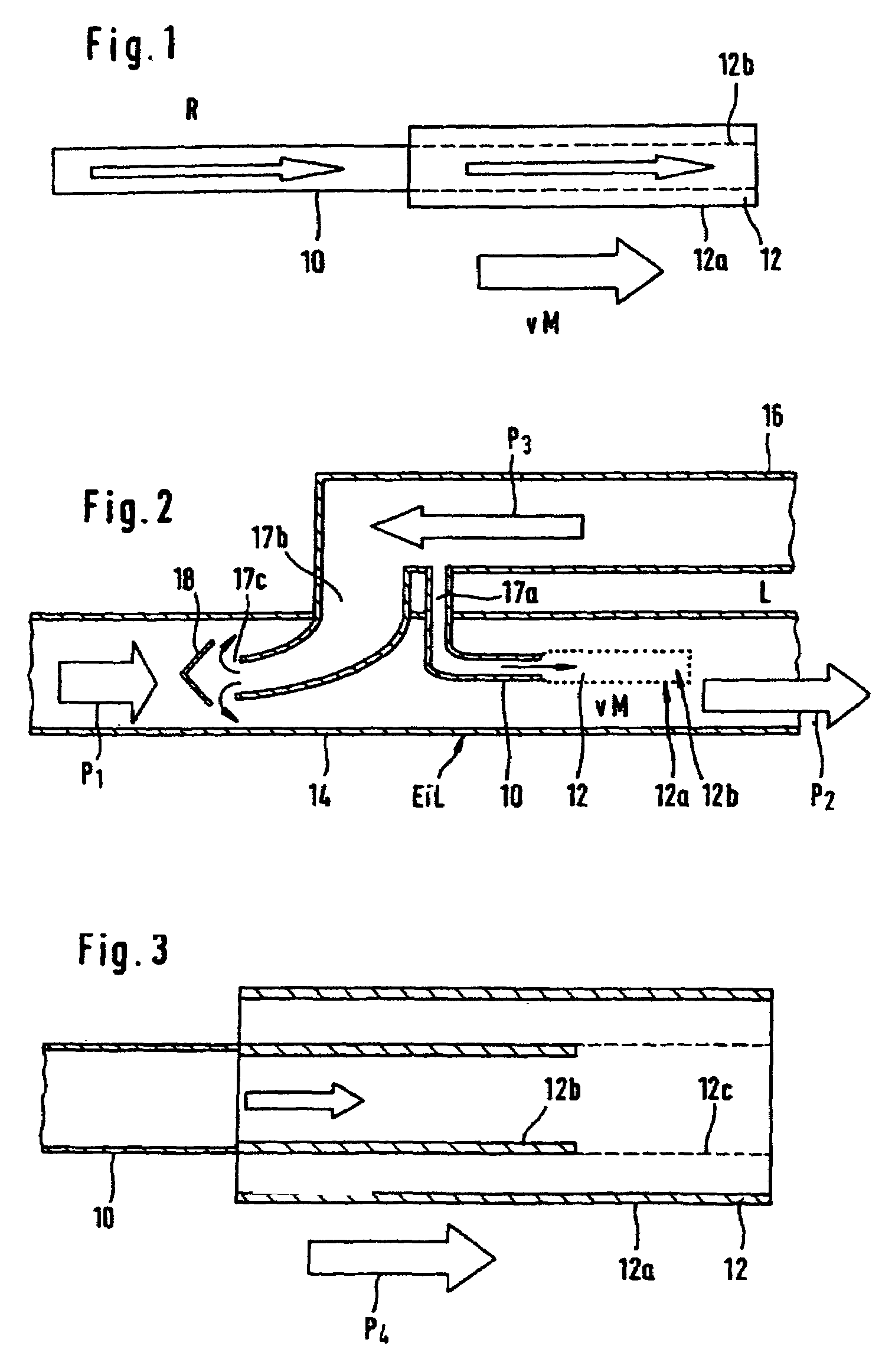
[0021]With reference to FIG. 1, there is shown a tubular sensor unit 12 which has been applied to a feed pipe 10. The outer side of the sensor unit 12 is designed as the outer electrode 12a or first sensor, and the inner side is designed as an inner electrode 12b or second sensor. The respective electrodes are applied to a selectively ion-conducting material. An evaluation unit which is operatively connected to the sensor unit 12 through the sensors 12a, 12b thereof is not illustrated.

[0022]The membranes which have been applied to the inner and outer sides (12a, 12b) are selectively conductive with respect to an ionised gas which is present in the atmospheres which are to be considered, as will now be explained in more detail with reference to FIG. 2.

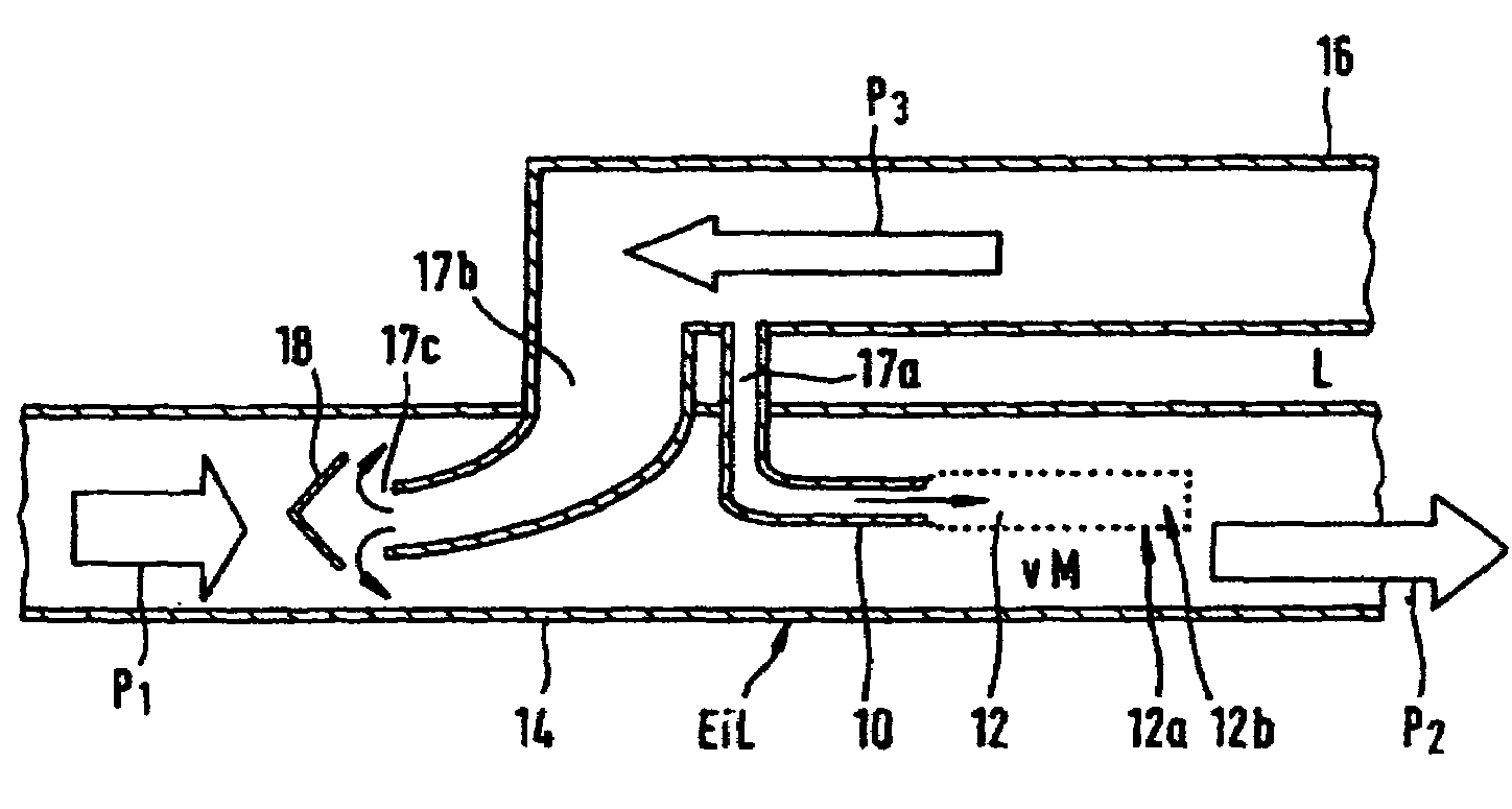
[0023]In FIG. 2, an intake line or manifold in which the sensor unit according to the present invention is arranged is denoted by 14. Arrow P1 indicates that fresh air enters the manifold 14 (from the left in the illustration shown in F...


PUM


Abstract

In a device for determining an exhaust gas recirculation rate (EGR) in an internal combustion engine, wherein the device includes a sensor unit, which in a first region is exposed to an exhaust-gas atmosphere from an exhaust gas recirculation line and in a second region is exposed to an exhaust gas / fresh air atmosphere in an intake line of the internal combustion engine downstream of a location where the exhaust gas recirculation line opens into the intake line, the sensor unit disposed in the intake line is tubular with the inner side of the sensor unit being exposed to the exhaust gas atmosphere and the outer side of the sensor unit being exposed to the exhaust gas / fresh air atmosphere. The sensor unit is preferably positioned centrally within the intake line away from the wall of the intake line.

Description

CROSS-REFERENCE TO RELATED APPLICATION[0001]This is a continuation-in-part application of international application PCT / EP03 / 07031 filed Jul. 2, 2003 and claiming the priority of German application 102 33 362.9 filed Jul. 23, 2002.BACKGROUND OF THE INVENTION[0002]The present invention relates to emission control apparatus for an internal combustion engine, and, in particular, to a device for determining the exhaust gas recirculation rate of an internal combustion engine.[0003]One known way of lowering NOx emissions from spark-ignition or diesel engines is what is known as exhaust gas recirculation (EGR). In particular, the temperature-sensitive NOx emission is reduced by admixing exhaust gases to the fresh air prior to combustion. Usually, exhaust gas is added to an intake line from an exhaust pipe of the internal combustion engine via an exhaust gas recirculation line. The recirculation rate of the exhaust gas, i.e., the quantity of the exhaust gas stream which is admixed with the ...

Claims


Application Information

Patent Timeline
Patent Type & Authority Patents(United States)
IPC IPC(8): G01M19/00F02DF02M25/07F02D21/08F02M35/10G01M15/00G01M99/00
CPCF02D41/0072F02D41/144F02M25/0714F02M25/0755F02M35/10222F02M35/10393F02M25/072Y02T10/47F02M26/46F02M26/11F02M26/17Y02T10/40
Inventor AMMAN, MARKUSFEKETE, NIKOLASHERBSTRITT, DIRKKNEZEVIC, ALEKSANDARMULLER, RALFPLOG, CARSTEN
Owner DAIMLER AG
Why Eureka
Try Eureka