Engine air intake manifold

a technology for air intake and engine, which is applied in the direction of air intake for fuel, combustion-air/fuel-air treatment, machines/engines, etc., can solve the problems of increasing affecting the arrangement of other parts, and affecting so as to reduce the number of parts and weight, prevent the contamination of the throttle valve, and improve the control response of secondary additive gases

Active Publication Date: 2006-09-05
NISSAN MOTOR CO LTD
View PDF22 Cites 9 Cited by
  • Summary
  • Abstract
  • Description
  • Claims
  • Application Information

AI Technical Summary

Benefits of technology

[0014]One object of the present invention is to provide an engine air intake manifold configured to introduce a secondary additive gas, and that is configured to reduce the number of parts and the weight.
[0015]Another object of the present invention is to provide an air intake manifold configured to introduce a secondary additive gas, and that prevents contamination of the throttle valve and the inside of the air intake passages and that improves the control response of the secondary additive gas.
[0016]Yet another possible object of the present invention is to provide an air intake manifold in which a mounting block for mounting an air intake control valve is installed inside the downstream side of the air intake branch pipe(s) and a secondary additive gas can be introduced on the downstream side of the mounting block without increasing the size of the mounting flange provided for mounting the air intake manifold to the engine main body.
[0017]Regarding an engine air intake manifold provided with a gas passage for delivering a secondary additive gas to the intake air flowing through the air intake manifold, the object of the present invention is to increase the degree of uniformity with which the air intake manifold distributes the secondary additive gas to the cylinders of the engine by using a chamber to absorb pulsations and pressure fluctuations.

Problems solved by technology

As a result, there is the possibility that the cost and weight will rise due to the increased number of parts.
Also, since the gas passages are formed on the outside of the air intake branch parts, the structure becomes complex and there is the possibility that the space occupied by the gas passages (equal in number to the cylinders) will hinder the arrangement of other parts.
In the case of the air intake manifold disclosed in Japanese Laid-Open Patent Publication No. 2001-123901, there is the possibility that the inside of the air intake passages will be contaminated because of the introduction of EGR gas inside the collector.
Furthermore, the control response is poor because the EGR gas is introduced inside the collector, which is far from the cylinders.
When the EGR gas is introduced into the intake air as described in Japanese Laid-Open Patent Publication No. 2001-123901, the distribution to the cylinders is not stable because it is affected by intake pulsation.
More specifically, although the EGR gas distribution pipe is provided with a distribution hole for each cylinder, an intake pulsation that occurs at the distribution hole corresponding to one cylinder cannot be absorbed inside the EGR gas distribution pipe and affects the EGR gas delivered from the distribution holes corresponding to the adjacent cylinders, making it difficult to maintain the uniformity of the secondary additive gas distribution to the cylinders.
Moreover, it has been discovered that when an intake control valve is arranged in a downstream portion of the air intake manifold to impart a strong gas flow to the intake air flowing into the combustion chamber, it is possible that the intake control valve will be contaminated and suffer a malfunction if a secondary additive gas is introduced upstream of the intake control valve.
Consequently, the mounting flange or spacer must be enlarged in the vertical direction and the mating face of the engine main body must be increased to accommodate the increased size of the mounting flange or spacer, making it more difficult to reduce size and weight.
Consequently, shrinkage cavities occur more readily and the engine main body is difficult to cast.

Method used


Image

  • Engine air intake manifold
  • Engine air intake manifold
  • Engine air intake manifold

Examples


first embodiment

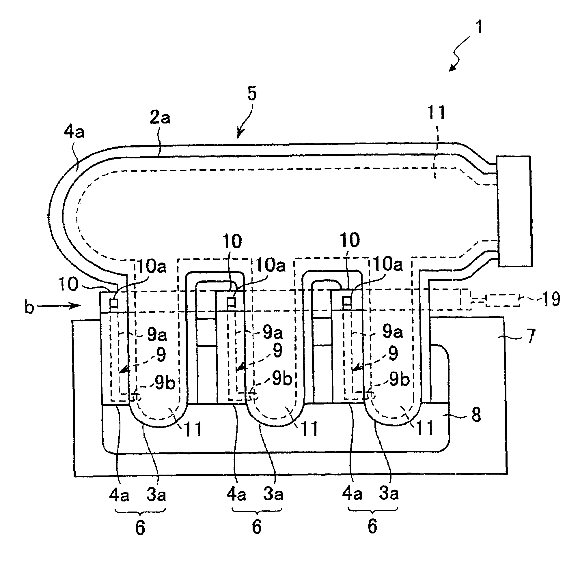
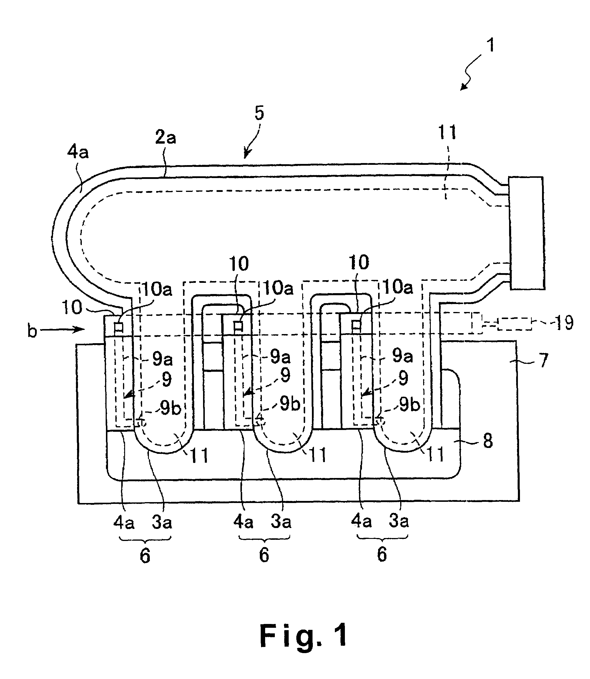
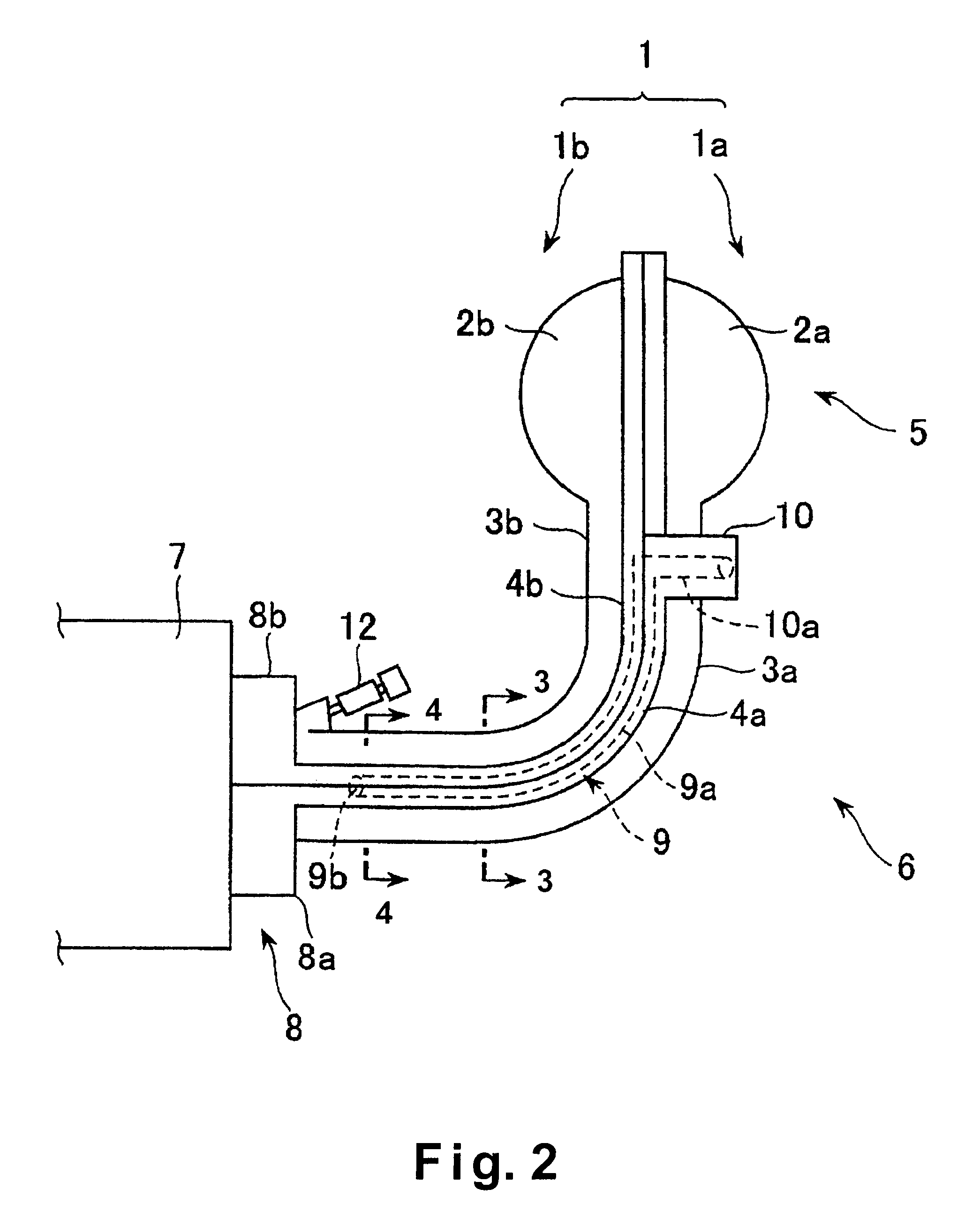
[0049]Referring initially to FIGS. 1–5, an air intake manifold 1 is illustrated in accordance with a first embodiment of the present invention. The air intake manifold 1 is configured and arranged for a multiple cylinder engine. This air intake manifold 1 is made of thermoplastic or thermosetting resin, and basically includes a pair (first and second) of main body sections 1a and 1b that are fixedly coupled together. Basically, the first main body section 1a includes a semi-cylindrical air intake passage forming part 2a, a plurality of semi-cylindrical air intake passage forming parts 3a that branch from the air intake passage forming part 2a, and a first flange part 4a formed in a radially protruding manner along the mating faces of the air intake-forming parts 2a and 3a. Similarly, the second main body section 1b includes a semi-cylindrical air intake passage forming part 2b, a plurality of semi-cylindrical air intake passage forming parts 3b that branch from the air intake passag...

second embodiment

[0062]Referring now to FIGS. 6–8, an air intake manifold 201 in accordance with a second embodiment will now be explained. In view of the similarity between the first and second embodiments, the parts of the second embodiment that are identical to the parts of the first embodiment will be given the same reference numerals as the parts of the first embodiment. Moreover, the descriptions of the parts of the second embodiment that are identical to the parts of the first embodiment may be omitted for the sake of brevity.

[0063]Basically, the air intake manifold 201 is identical to the air intake manifold 1, except that (1) the main body sections 1a and 1b are mated tightly together along a different mating plane which results in a single engine main body mounting flange 8 and a modified gas passage 9, and (2) a fuel injection device 12 has been added for each cylinder. Similarly to the first embodiment, this air intake manifold 201 includes a collector 5, a plurality of air intake branch...

third embodiment

[0070]Referring now to FIGS. 9–13, an air intake manifold 301 is illustrated in accordance with a third embodiment of the present invention. In view of the similarity between this embodiment and the prior embodiments, the descriptions of the parts of this embodiment that are identical to the parts of the first embodiment may be omitted for the sake of brevity.

[0071]Basically, the air intake manifold 301 is identical to the air intake manifold 201, except that (1) the cylindrical part 3c has been modified and (2) the introducing parts 10 have been replaced with a chamber unit 14. Similarly to the first and second embodiments, this air intake manifold 301 includes a collector 5, a plurality of air intake branch pipes 6 that branch from the collector 5, and a mounting flange 8 for mounting to an engine main body 7. Similarly to FIG. 1, air intake passages 11 of the air intake manifold 301 are formed inside the collector 5 and the air intake branch pipes 6. As shown in FIG. 9, the air i...


PUM

PropertyMeasurementUnit
weightaaaaaaaaaa
sizeaaaaaaaaaa
shrinkageaaaaaaaaaa

Abstract

An engine air intake manifold has two main body sections that are divided along an airflow direction and mated tightly against each other at oppositely facing mating parts so as to form an air intake passage therein. A gas passage is formed along the mating parts. The gas passage opens into a downstream portion of the air intake passage and supplies a secondary additive gas thereto. Preferably, the engine air intake manifold has air intake branch pipes with valve mounting blocks for mounting air intake control valves to a downstream portion of the air intake branch pipes.

Description

BACKGROUND OF THE INVENTION[0001]1. Field of the Invention[0002]The present invention relates to an air intake manifold for an engine. More particularly, the present invention relates to an engine air intake manifold having first and second main body sections that are divided along an airflow direction and form an air intake passage therebetween. The first and second main body sections have oppositely facing mating parts that form a gas passage for supplying a secondary additive gas to the intake air flowing inside the air intake manifold. Preferably, the engine air intake manifold includes an air intake branch pipe with a mounting block for mounting an air intake control valve that is inserted into a downstream portion of the air intake branch pipe.[0003]2. Background Information[0004]An air intake manifold for a multiple cylinder engine generally has a collector into which intake air is introduced to the cylinders. The air intake manifold has a plurality of air intake branch parts...

Claims


Application Information

Patent Timeline
Patent Type & Authority Patents(United States)
IPC IPC(8): F02M35/10F02M25/06F02M25/07
CPCF02M25/06F02M25/0703F02M25/0727F02M25/0747F02M25/0748F02M35/10111F02M35/10222F02M35/10321F02M35/10347F02M35/10144Y02T10/121F02M35/10216F02M35/112F02M35/116F02M26/12F02M26/23F02M26/41F02M26/42Y02T10/12
Inventor UCHIYAMA, SHIGEKI
Owner NISSAN MOTOR CO LTD
Why Eureka
Try Eureka