Magnetic fluid seal device
a magnetic fluid and seal device technology, applied in the direction of engine seals, mechanical devices, engine components, etc., can solve the problems of magnet and pole pieces having to be adhered, and the difficulty of managing the amount of magnetic fluid
- Summary
- Abstract
- Description
- Claims
- Application Information
AI Technical Summary
Benefits of technology
Problems solved by technology
Method used
Image
Examples
fourth embodiment
[0146]FIG. 4 illustrates a magnetic fluid seal device in accordance with a fourth embodiment. The fourth embodiment is one in which cutout portions 12 are formed in center portions of the inner and outer peripheral surfaces, in addition to the cutout portion 11 in the radial-direction side surface of the annular magnet 3. Other configurations are the same as those of the first embodiment.
[0147]Similar to the third embodiment, the cutout portion 11 is formed in the portion of the annular magnet 3 that does not contact the magnetic fluids 4 and 5 (i.e., in the radial-direction side surface of the annular magnet 3 excluding corner portions and extending between the housing 1 and the shaft 2).
[0148]In addition, the cutout portions 12 are formed in the center portions of the inner and outer peripheral surfaces opposing the housing 1 or the shaft 2 excluding the corner portions of the annular magnet 3.
[0149]Thus, weight reduction of the annular magnet 3 is improved, and the annular magnet...
fifth embodiment
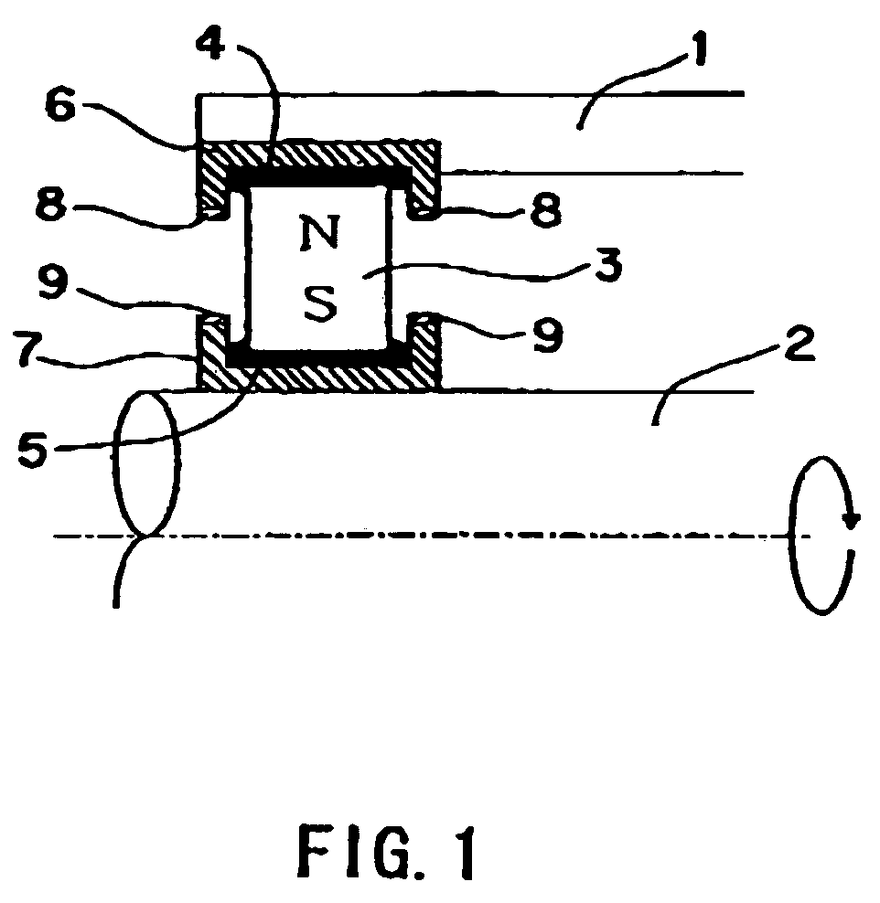
[0150]FIG. 5 illustrates a magnetic fluid seal device in accordance with a fifth embodiment. The fifth embodiment is one in which no groove is formed in a sleeve 71 fitted together with the shaft 2 and in which the oil-repellant film 9 is formed on both axial-direction end portions of opposing surfaces opposing the annular magnet 3. Other configurations are the same as those of the first embodiment.
[0151]The sleeve 71 fitted together with the shaft 2 is a cylindrical shape that does not have formed therein a groove such as the one in the first embodiment. The oil-repellant film 9 is formed on both of the axial-direction end portions of opposing surfaces opposing the annular magnet 3.
[0152]In this configuration also, the annular magnet 3 floats with a magnetic force with respect to any orientation, and functions as a dust seal with respect to the rotation of the shaft 2.
[0153]It should be noted that, as an alternative to the present embodiment, similar effects can be obtained by not ...
sixth embodiment
[0154]FIG. 6 illustrates a magnetic fluid seal device in accordance with a sixth embodiment. The sixth embodiment is one in which relative reciprocal movement is conducted between the housing 1 and the shaft 2, a sleeve 72 fitted together with the shaft 2 is extended in the axial direction to a reciprocal movement length, and an oil-repellant film 13 is formed on the entire opposing surface opposing the annular magnet 3. Other configurations are the same as those of the first embodiment.
[0155]In the present embodiment, not only is relative rotational movement conducted between the housing 1 and the shaft 2, but relative reciprocal movement is also conducted between the housing 1 and the shaft 2, and, in the present embodiment, the shaft 2 reciprocally moves.
[0156]Thus, it is necessary to stabilize and support the magnetic fluid seal device by sliding the magnetic fluid, and, in the present embodiment, the device has a configuration in which the sleeve 72 fitted together with the sha...
PUM
 Abstract
Description
Claims
Application Information
 - R&D
- Intellectual Property
- Life Sciences
- Materials
- Tech Scout
- Unparalleled Data Quality
- Higher Quality Content
- 60% Fewer Hallucinations
Browse by: Latest US Patents, China's latest patents, Technical Efficacy Thesaurus, Application Domain, Technology Topic, Popular Technical Reports.
© 2025 PatSnap. All rights reserved.Legal|Privacy policy|Modern Slavery Act Transparency Statement|Sitemap|About US| Contact US: help@patsnap.com


