
Motor vehicle powertrain control method for low traction conditions

a technology for motor vehicles and powertrains, applied in the direction of process and machine control, braking systems, instruments, etc., can solve the problems of system implementation costs, and achieve the effect of reducing the likelihood of wheel slippage during the vehicle and reducing the disturbance of output torqu

Inactive Publication Date: 2006-09-05
GM GLOBAL TECH OPERATIONS LLC
View PDF12 Cites 21 Cited by
  • Summary
  • Abstract
  • Description
  • Claims
  • Application Information

AI Technical Summary

Benefits of technology

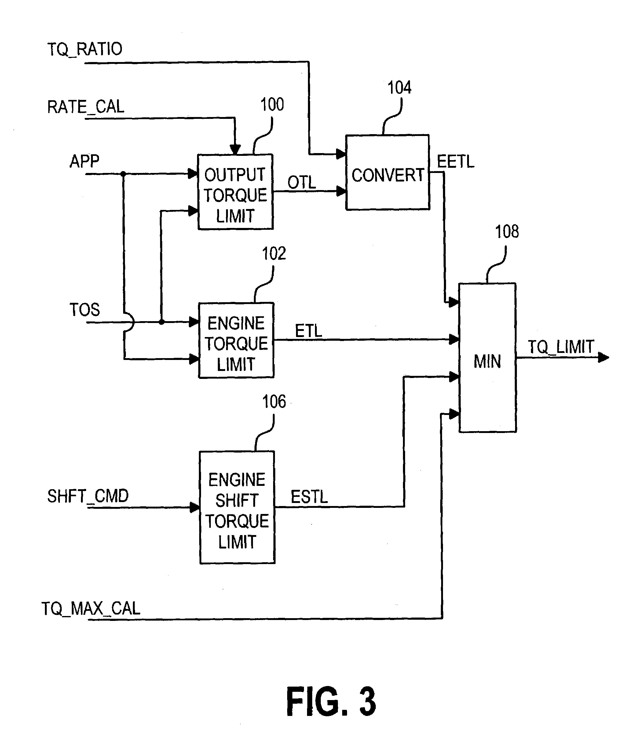
[0003]The present invention is directed to a low-cost driver-initiated method of limiting the drive torque of a motor vehicle for the purpose of reducing the likelihood of wheel slip during vehicle operation on low traction road surfaces. The driver initiates a low traction control mode by actuating a control panel switch or by moving the transmission range selector to a Low range setting while the vehicle is substantially stopped, and terminates the control by further actuation of the switch or by returning the range selector back to the normal forward range setting (i.e., Drive). While active, the low traction control mode interfaces with an engine controller to limit the drive torque, so long as cruise control is inactive, the accelerator pedal setting is less than a reference level, and the transmission is operating in a gear other than its top gear or gears. In operation, the engine torque is limited as required to limit the drive wheel torque and its rate of change, and to reduce the output torque disturbance due to transmission shifting. When the low traction control mode is terminated, the engine torque limits are progressively removed in a way that does not produce perceptible acceleration or deceleration of the vehicle.

Problems solved by technology

However, such systems can be expensive to implement, particularly in applications where vehicle sensors and / or actuators must be added to support the traction control function.

Method used


Image

  • Motor vehicle powertrain control method for low traction conditions
  • Motor vehicle powertrain control method for low traction conditions
  • Motor vehicle powertrain control method for low traction conditions

Examples


Embodiment Construction

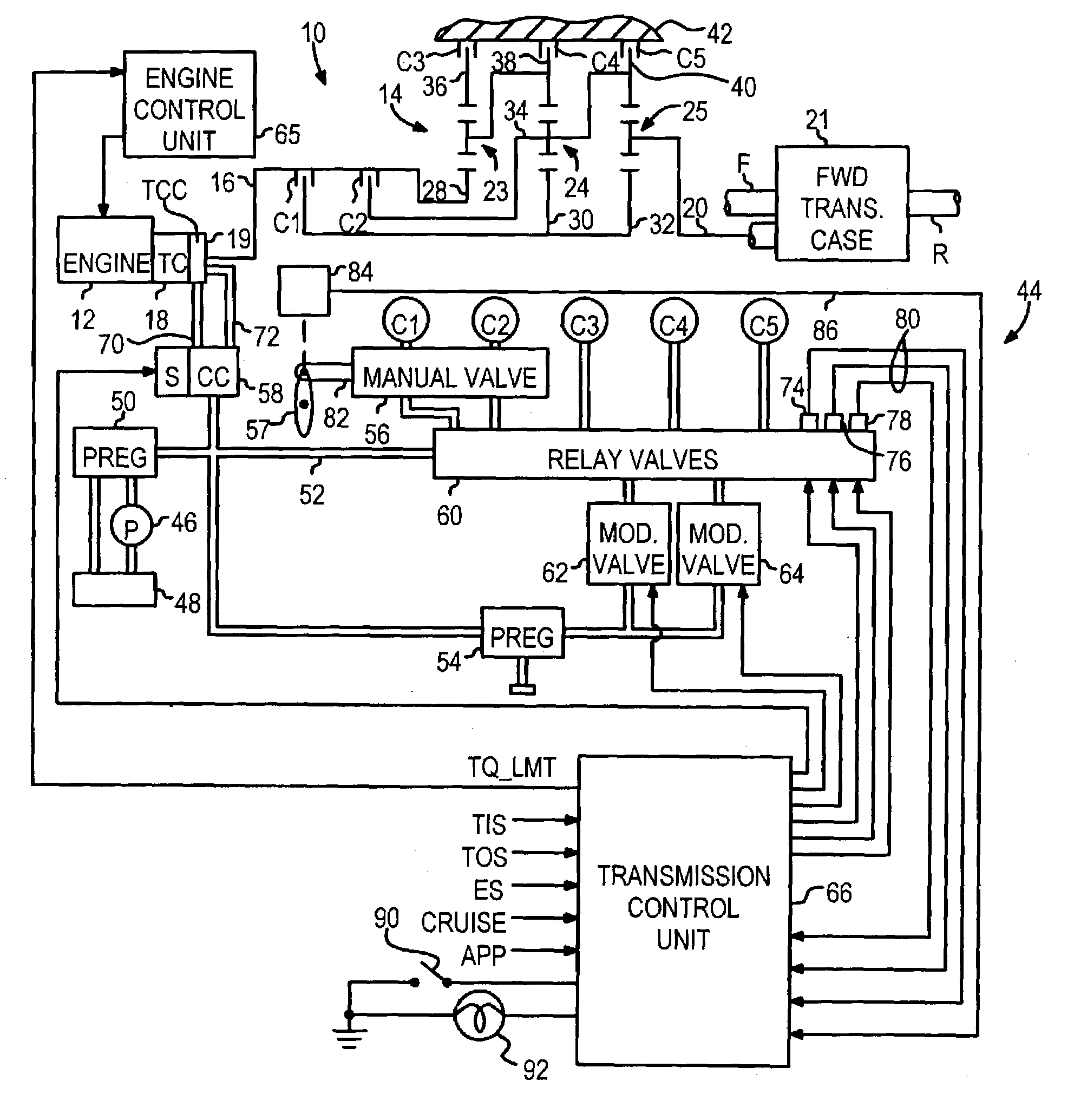
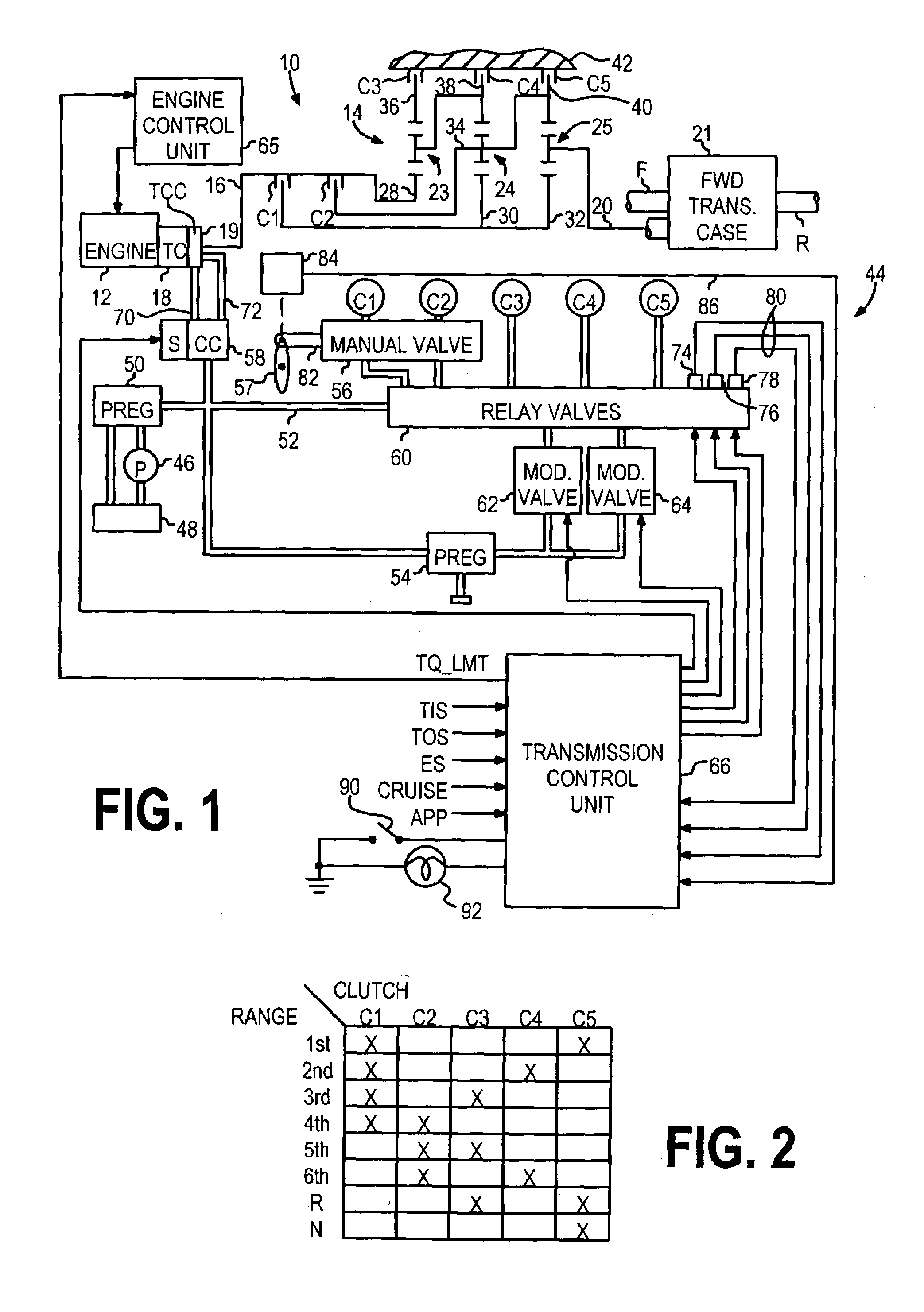
[0008]The control of this invention is described in the context of a motor vehicle powertrain 10 including a conventional internal combustion engine 12 and an automatic transmission 14. The transmission 14 is preferably of the type described in the U.S. Pat. No. 4,070,927 to Polak, with an electro-hydraulic control of the type described in U.S. Pat. No. 5,601,506 to Long et al. Accordingly, the transmission and control elements shown in FIG. 1 hereof have been greatly simplified, it being understood that further detail regarding the fluid pressure routings and so forth may be found in the aforementioned patents.

[0009]Referring to FIG. 1, the engine 12 is coupled to an input shaft 16 of transmission 14 through a fluidic torque converter (TC) 18 that is provided with a clutch (TCC) 19 that is selectively engaged to establish a mechanical coupling. The transmission output shaft 20 is coupled to the driving wheels of the vehicle in one of several conventional ways. The illustrated embod...


PUM


Abstract

A driver-initiated low traction control method limits the drive torque of a motor vehicle during operation on low traction road surfaces. The low traction control mode is initiated by actuation of a switch or by moving a transmission range selector to a Low range while the vehicle is substantially stopped, and terminated by further actuation of the switch or by returning the range selector back to the Drive setting. The low traction control mode limits the engine torque as required to limit the drive wheel torque and its rate of change, so long as cruise control is inactive, the accelerator pedal setting is less than a reference level, and the transmission is operating in a gear other than its top gear. When the low traction control mode is terminated, the engine torque limits are progressively removed in a way that does not produce perceptible acceleration or deceleration of the vehicle.

Description

TECHNICAL FIELD[0001]This invention relates to a powertrain control for a motor vehicle, and more particularly to a control method that limits the vehicle drive torque during operation on low traction road surfaces.BACKGROUND OF THE INVENTION[0002]Many motor vehicles are equipped with automatic traction control systems that reduce the tractive effort of the vehicle through engine torque reduction and / or wheel braking when excessive wheel spin is detected. However, such systems can be expensive to implement, particularly in applications where vehicle sensors and / or actuators must be added to support the traction control function. Accordingly, what is needed is a low-cost traction control method that limits the vehicle drive torque during operation on low traction road surfaces.SUMMARY OF THE INVENTION[0003]The present invention is directed to a low-cost driver-initiated method of limiting the drive torque of a motor vehicle for the purpose of reducing the likelihood of wheel slip dur...

Claims


Application Information

Patent Timeline
IPC IPC(8): B60W10/04B60W10/06B60W10/115B60W30/188
CPCB60K41/062B60W10/06B60W10/115B60W30/188B60K2741/065Y10T477/68B60W2540/103B60W2710/0666B60W2710/105Y10T477/675Y10T477/688B60W2540/10
Inventor KRESSE, JOHN P.HITCH, RONALD P.HUBBARD, GREGORY A.
Owner GM GLOBAL TECH OPERATIONS LLC
Learn More