Highly oriented super microfilaments

a super microfilament, high-oriented technology, applied in the direction of manufacturing tools, electric/magnetic/electromagnetic heating, melting methods, etc., can solve the problems of inability to draw simply and conveniently, high cost, etc., to achieve easy electrostatic treatment, high heat resistance, and high quality application use

Inactive Publication Date: 2006-09-05
YAMANASHI UNIV OF
View PDF9 Cites 21 Cited by
  • Summary
  • Abstract
  • Description
  • Claims
  • Application Information

AI Technical Summary

Benefits of technology

[0005]For the original filament of this invention, any of filaments consisting of thermoplastic polymers such as polyesters including polyethylene terephthalate, polyamide including nylon (including nylon 6, nylon 66), polyolefins including polypropylene and polyethylene, polyvinyl alcohol polymers, acrylonitrile polymers, fluoro polymers, vinyl chloride polymers, styrene polymers, polyoxymethylene and ether ester polymers, can be used. Among them, polyethylene terephthalate, nylon (including nylon 6 and nylon 66) and polypropylene have good drawability and molecular mobility, and are particularly suitable for the drawing of this invention.
[0022]When the drawn filaments of this invention are isotactic polypropylene, highly molecular orientated super micro polypropylene filaments can be formed characterized in that the a birefringence is 20×10−3 or more and, preferably 25×10−3 or more and a diameter of 5 μm or less and, preferably 3 μm or less and most preferably 2 μm or less. Since polypropylene has water repellency and chemical resistance and has various properties such as easy to apply electrostatic treatment, when it is formed into highly oriented super microfilaments, development in various industrial application uses such as filters can be expected.

Problems solved by technology

However, since special and complicate spinning methods such as islands-in-a-sea type fiber spinning (for example, Japanese Patent Laid-Open No.
Hei 7-258940) or spinning by dividual fibers (for example, Japanese Patent Laid-Open No. 2002-220740) have been used, for the production of highly oriented super micro filaments and having high quality with the filament diameter of 5 μm or less, they are expensive and cannot be drawn simply and conveniently by using general-purpose fibers.

Method used


Image

  • Highly oriented super microfilaments
  • Highly oriented super microfilaments
  • Highly oriented super microfilaments

Examples


example 1

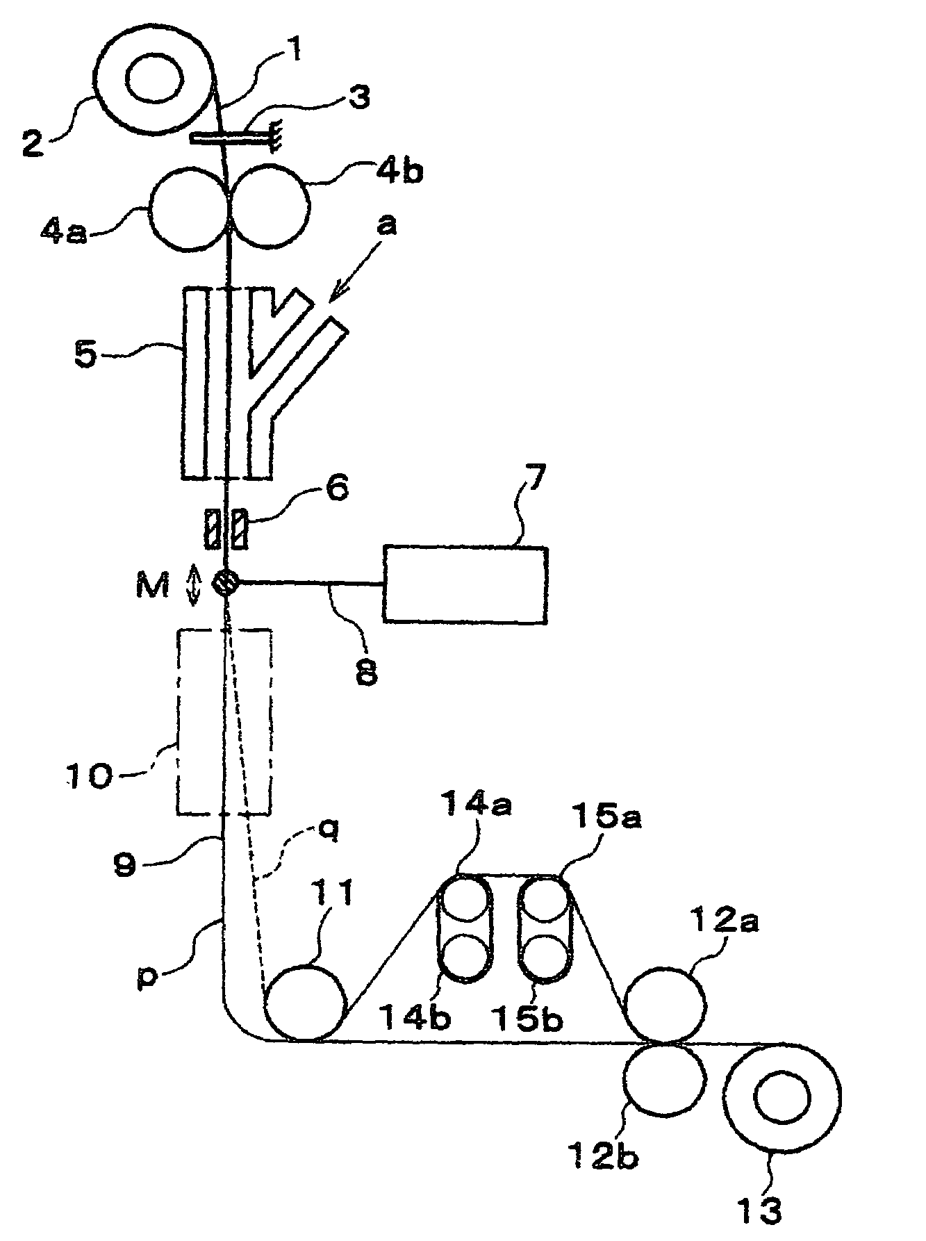
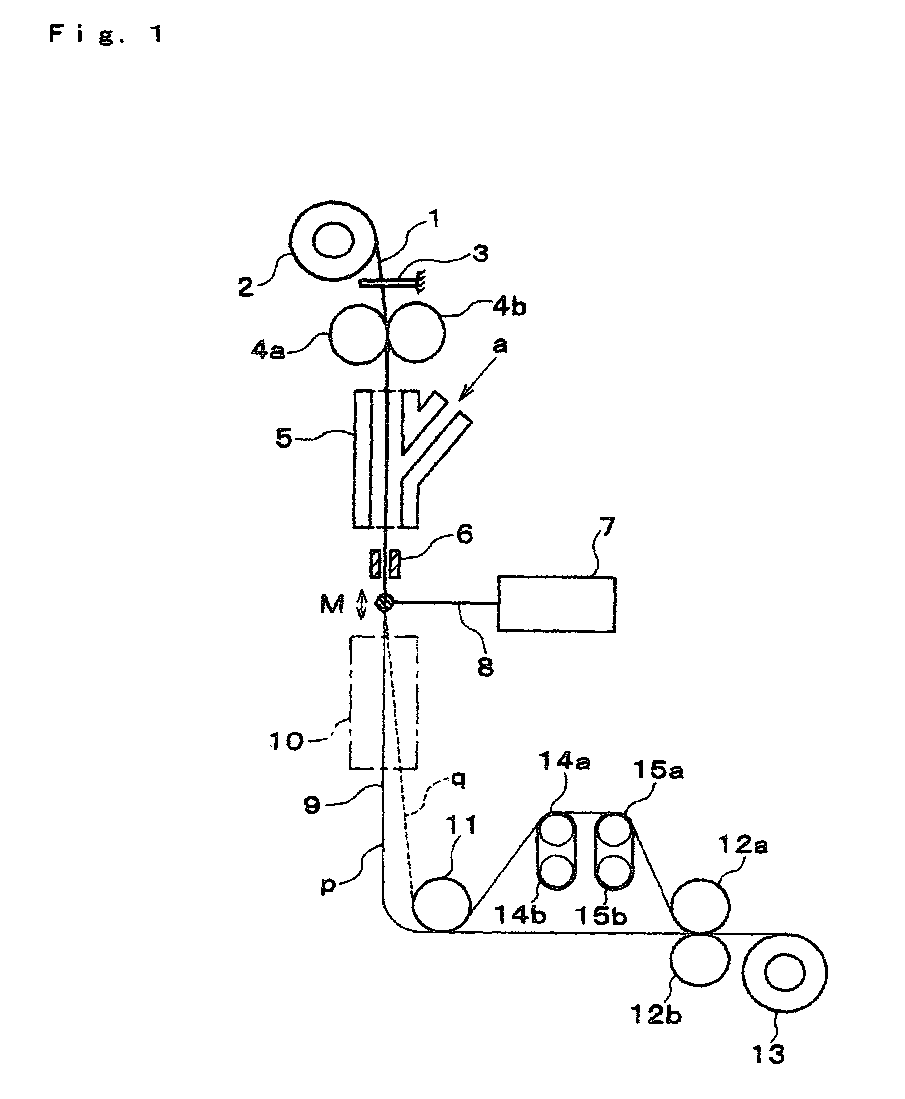
[0036]Undrawn nylon 6 filaments (diameter 185 μm, birefringence of 6.25×10⁻³, degree of crystallinity of 27.6% (based on density by floatation technique) were used as original filaments and drawn by the apparatus shown in FIG. 1. The filaments were drawn at a supplying speed of 0.47 m / min and a wind-up speed of 1414 m / min. In this case, a carbon dioxide gas laser emitter manufactured by Onizuka Glass Co., Ltd. with a maximum power of 10 W was used for the laser emitter. The laser power density was 23.7 W / cm2 and the beam diameter was 4.0 mm. The drawn filaments ran along the trace p in FIG. 1 and the distance from the laser-heating portion M to the lowermost position was 150 cm. The obtained drawn filament had a diameter of 3.16 μm (draw ratio: 3427) and a birefringence of 44.12×10⁻³. Comparison between the original filament and the drawn filament is shown by a scanning electron microscopic (SEM) photograph of FIG. 4. FIGS. 5 and 6 show a relation between the diameter and the birefr...

example 2

[0037]Undrawn polyethylene terephthalate filaments (diameter of 240 μm, birefringence of 0.5×10⁻³, amorphous and isotropic state were confirmed by wide angle X-ray diffraction photography) were used and drawn by the apparatus shown in FIG. 1. The laser emitter is identical with that in Example 1. The filaments were drawn at a supplying speed of 0.30 m / min and a wind-up speed of 1400 m / min. In this case, the laser power density was 1.91 W / cm2 and the beam diameter was 4.0 mm. The drawn filaments ran along the trace q in FIG. 1 and the drawing tension at that time was 0.45 MPa when estimated from the batchwise system in the prior application. The obtained drawn filament had a diameter of 3 μm (draw ratio: 6400) and a birefringence of 38.0×10⁻³. Table of FIG. 7 shows a relation between diameters, a birefringence and a laser power density in a case of changing the supplying speed and the take-up speed variously for the original filaments.

example 3

[0038]Undrawn isotactic (it) polypropylene filaments (diameter of 211.0 μm, a birefringence of 0.3×10⁻³ and a degree of crystallinity of 47%) were used as original filaments and drawn by the apparatus shown in FIG. 1. The original filaments were obtained by melt spinning from pellets of Ace Polymer Co., Ltd. (Mw=3×10⁵, Mw=5×10⁴) The laser emitter is identical with that in Example 1. The filaments were drawn at a supplying speed of 0.38 m / min and at a wind-up speed of 1386.9 m / min. The drawn filaments ran along a trace q in FIG. 1 and the drawing tension in this case was 0.33 MPa as estimated from the batchwise system in the prior application. The obtained drawn filament had a diameter of 3.8 μm (draw ratio: 3082), and a birefringence of the filament was 25.6×10⁻³. For the original filaments, FIG. 8 shows a relation between the diameter and the birefringence in a case of changing the supplying speed and the wind-up speed variously.


PUM

PropertyMeasurementUnit
diameteraaaaaaaaaa
wavelengthaaaaaaaaaa

Abstract

Method of and apparatus for continuously manufacturing highly oriented super micro filaments with a diameter of 5 μm or less from most of thermoplastic polymers stably by a simple and convenient means without requiring any special apparatus of high accuracy and high level, characterized in original filaments supplied from a filament supply means are heated by infrared beams and the heated filaments are drawn by tension provided by their own weight or under an applied tension of 1 MPa or less, and are drawn to 1000 times or more.

Description

1. TECHNICAL FIELD OF THE INVENTION[0001]This invention concerns a method of and an apparatus for manufacturing drawn filaments and it also relates to highly oriented super microfilaments drawn at a high draw ratio of 1000 times or more and obtained by the drawing method.2. BACKGROUND ART[0002]Super microfilaments have been used in various applications such as artificial leathers, wiping cloths or filters. However, since special and complicate spinning methods such as islands-in-a-sea type fiber spinning (for example, Japanese Patent Laid-Open No. Hei 7-258940) or spinning by dividual fibers (for example, Japanese Patent Laid-Open No. 2002-220740) have been used, for the production of highly oriented super micro filaments and having high quality with the filament diameter of 5 μm or less, they are expensive and cannot be drawn simply and conveniently by using general-purpose fibers.[0003]On the other hand, as a method of obtaining fibers of high tensile strength and high tensile mod...

Claims


Application Information

Patent Timeline
Patent Type & Authority Patents(United States)
IPC IPC(8): D01F6/00B29C35/08B65H54/64D01D5/08D02J1/22D02J13/00D04H3/016D04H3/02
CPCD02J1/22D04H3/02D02J13/00Y10T428/2913
Inventor SUZUKI, AKIHIRO
Owner YAMANASHI UNIV OF
Why Eureka
Try Eureka