
Piezoelectric device and its manufacturing method

a piezoelectric device and manufacturing method technology, applied in piezoelectric/electrostrictive devices, piezoelectric/electrostrictive/magnetostrictive devices, device material selection, etc., can solve the problem of not obtaining good piezoelectric characteristics, difficult to obtain a sufficient precision by positioning the head using only the conventional voice coil motor, etc., to achieve enhanced piezoelectric characteristics, favorable piezoelectric characteristics, and high speed

Inactive Publication Date: 2006-09-05
PANASONIC CORP
View PDF10 Cites 8 Cited by
  • Summary
  • Abstract
  • Description
  • Claims
  • Application Information

AI Technical Summary

Benefits of technology

[0010]The present invention is based on the finding that an appropriate oxygen deficiency amount for an oxide piezoelectric thin film contributes to an improvement of the piezoelectric constant d31 and the realization of a piezoelectric device having favorable piezoelectric characteristics, and hence, presents a piezoelectric device having excellent piezoelectric characteristics, an increased film forming speed, and an enhanced mass productivity, and a method of manufacturing the same.
[0014]By using the oxide piezoelectric thin film having such an oxygen deficiency, a piezoelectric device having a more favorable piezoelectric characteristic than before can be obtained, and the film can be formed at a high speed, and hence, the characteristics of the piezoelectric device are enhanced, and improvement of mass productivity is realized.

Problems solved by technology

The piezoelectric device is used because the recording density of the magnetic disk is increased, the area of a recording region of one bit is decreased, and it is difficult to obtain a sufficient precision by positioning of the head using only the conventional voice coil motor.
Hence, good piezoelectric characteristics are not obtained, and the mass producibility is not improved.
Hence, mass productivity is not improved.

Method used


Image

  • Piezoelectric device and its manufacturing method
  • Piezoelectric device and its manufacturing method
  • Piezoelectric device and its manufacturing method

Examples


first exemplary embodiment

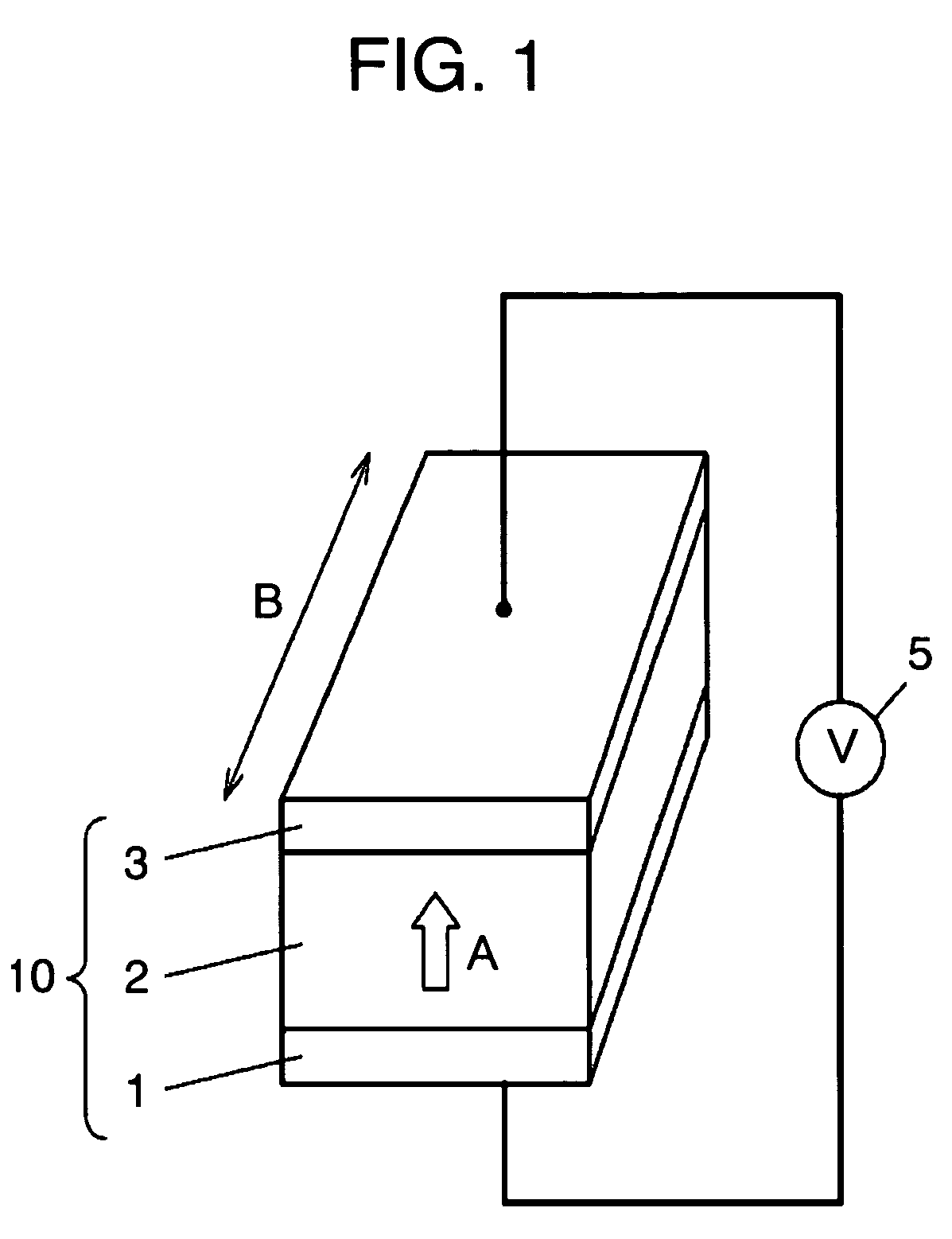
[0025]FIG. 1 is a perspective view of a piezoelectric device 10 in a first exemplary embodiment of the invention. FIG. 1 also shows a driving power source 5 for driving this piezoelectric device 10.

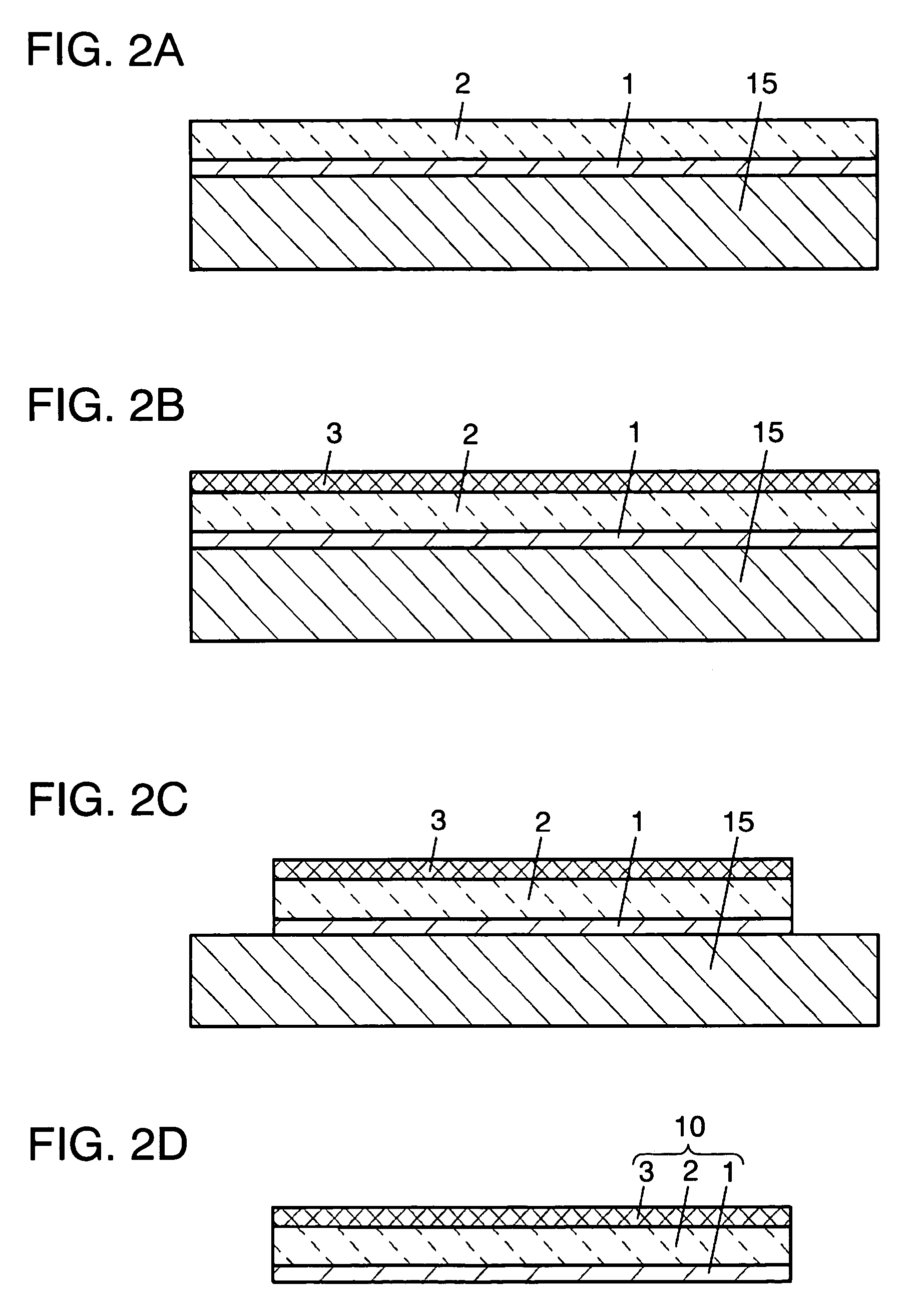
[0026]The piezoelectric device 10 comprises a first electrode film 1, an oxide piezoelectric thin film 2 formed on the first electrode film 1, and a second electrode film 3 formed on the oxide piezoelectric thin film 2. The first electrode film 1, oxide piezoelectric thin film 2, and second electrode film 3 are formed by thin film deposition technology such as sputtering, and processed in a nearly box shape as shown in FIG. 1 by photolithography and an etching process.

[0027]The piezoelectric device 10 measures, for example, about 2 mm in the expanding direction of the piezoelectric element, that is, in the length direction (direction B in the drawing), about 0.5 mm in width direction, and about 3 μm in thickness. For use as piezoelectric device 10, the oxide piezoelectric thin film 2 must...

second exemplary embodiment

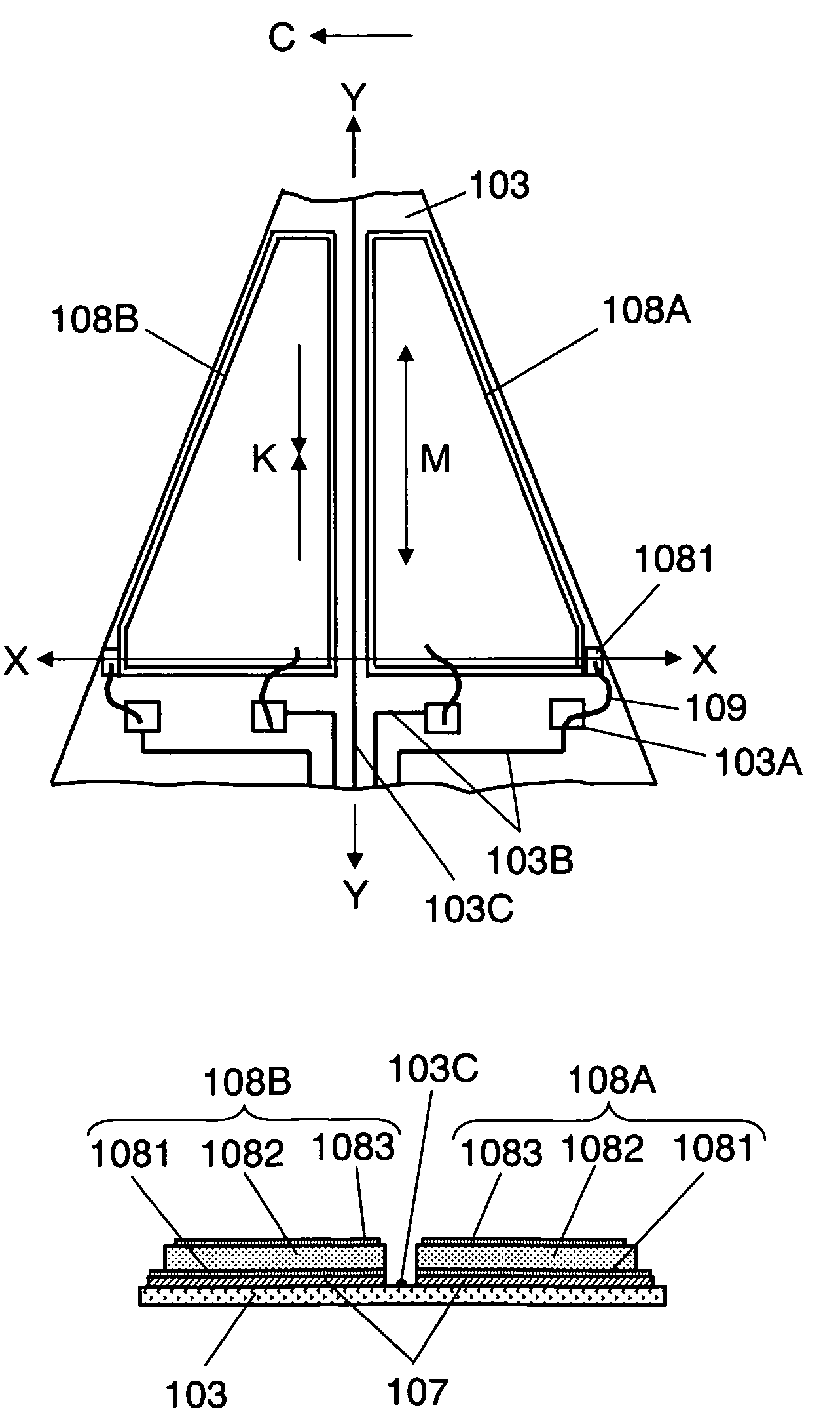
[0073]The second exemplary embodiment refers to a case of manufacturing an actuator composed of a piezoelectric device fabricated in the method explained in the first exemplary embodiment, and using this actuator for positioning a magnetic disk of a magnetic disk drive device. FIG. 7 is a schematic diagram of a device configuration using the piezoelectric device in this exemplary embodiment for positioning the magnetic head of a magnetic disk drive device. This magnetic disk drive device is characterized by a two-stage actuator configuration adding the actuator composed of the piezoelectric device of the invention to the actuator composed of a conventional voice coil motor. A head support mechanism 100 comprises a suspension 104 of a relatively low rigidity, a plate spring 105, an arm 106 of a relatively high rigidity, a flexure 103, a slider 102 mounted on this flexure 103 on the side facing a disk 200, a head (not shown) mounted on this slider 102, and a piezoelectric device 108 a...


PUM


Abstract

A piezoelectric device includes a first electrode film, a second electrode film, and a piezoelectric thin film enclosed by the first electrode film and second electrode film, in which the piezoelectric thin film is an oxide piezoelectric thin film having an oxygen deficiency amount of more than 0% and not more than 10% of the stoichiometric composition. The piezoelectric device composed of the piezoelectric thin film having such oxygen deficiency has a greater piezoelectric performance as compared with the oxide piezoelectric thin film in an oxidized state of stoichiometric composition, and by manufacturing under such a condition, the film forming speed is increased, so that the mass producibility can be improved.

Description

FIELD OF THE INVENTION[0001]The present invention relates to a piezoelectric device having a piezoelectric thin film, and its manufacturing method.BACKGROUND OF THE INVENTION[0002]Piezoelectric thin films are processed into various piezoelectric devices depending on their intended purpose, and are widely used as electronic components such as an actuator for deforming a device by applying a voltage, or a sensor for generating a voltage by deforming the device. For example, Japanese Laid-open Patent No. 2002-279742 discloses a technology of fine control of a head position in a magnetic disk by using a piezoelectric device. The piezoelectric device is used because the recording density of the magnetic disk is increased, the area of a recording region of one bit is decreased, and it is difficult to obtain a sufficient precision by positioning of the head using only the conventional voice coil motor. Accordingly, in addition to positioning by utilizing the voice coil motor, it has been c...

Claims


Application Information

Patent Timeline
Patent Type & Authority Patents(United States)
IPC IPC(8): H01L41/08H01L41/09H01L41/18H01L41/22
CPCH01L41/0805H01L41/316H01L41/1876H01L41/0986H10N30/206H10N30/8554H10N30/076H10N30/704
Inventor KITA, HIROYUKI
Owner PANASONIC CORP
Learn More