Apparatus and method for monitoring and/or analysis of electrical machines during operation

a technology of electrical machines and apparatuses, applied in the direction of mechanical energy handling, testing circuits, instruments, etc., to achieve the effect of low cost, sufficient accuracy, and physical simpl

Inactive Publication Date: 2006-09-05
GENERAL ELECTRIC TECH GMBH
View PDF20 Cites 36 Cited by
  • Summary
  • Abstract
  • Description
  • Claims
  • Application Information

AI Technical Summary

Benefits of technology

[0015]An object of the present invention is to provide an alternative apparatus for comprehensive detection of fault states in an electrical machine, which apparatus is sufficiently accurate and at the same time is physically simple, can be produced cheaply and is robust and which, in particular, allows continuous monitoring during normal operation. The present invention provides a device for monitoring and / or analysis of electrical machines during operation wherein the electrical machine has at least one generator with a shaft and drive means for driving this shaft, wherein the shaft is essentially directly grounded at the first end of the generator, and wherein a measurement unit for measurement of shaft voltage and / or shaft current as a function of time is provided on the shaft at the second end of the generator.
[0021]The fault states which can be accessed via this analysis unit by the measurement of the shaft voltage and / or shaft current are at least two different fault states selected from the following group: turns shorts in the rotor winding; functional weakness of the shaft grounding as well as insulation weakness in the shaft; insulation weakness in the rotor winding; spark erosion on the shaft; brush sparking, in particular on the sliprings; partial discharges in the stator and / or in the rotor and / or in the excitor apparatus; oscillations of the shaft, in particular torsional oscillations and / or bending oscillations and / or hunting; sparks in the excitation apparatus and / or the rotor winding; rotationally synchronous shattering marks and / or witness marks. Amazingly, all of these fault states are accessible via one such measurement and, in particular, it is in each case possible to monitor pairs or entire groups of these fault states synchronously and in a coordinated manner. At least one of the fault states is preferably radio-frequency spark activity such as spark erosion on the shaft or sparks in the excitation apparatus and / or the rotor winding, or dangerous oscillations of the shaft such as transverse bending oscillations, hunting or torsional oscillations. These combinations allow particularly powerful joint analyses.
[0022]One preferred embodiment of the apparatus is characterized in that a grounding unit is provided in order to ground the shaft at the first end of the generator, and itself allows the measurement of the shaft voltage and / or shaft current as a function of time. These signals (measured values) are also supplied to the analysis unit, are combined in the analysis unit and are evaluated simultaneously with the signals from the measurement unit. The additional measurement at the second end of the generator (or, in the case of two or more generators, at different points between these generators) by means of the measurement unit allows effective localization of fault states along the shaft. This makes it possible, for example, to find the bearing in which shaft erosion is actually occurring, since the differential behavior of the two measured values from the grounding unit and from the measurement unit allows conclusions to be drawn.
[0024]In a corresponding manner, it is advantageous, to filter the incoming signals to the analysis unit inter alia to improve the distinction between different phenomena and to improve the signal-to-noise ratio. These means may in this case be a low-pass filter and a radio-frequency bandpass filter, by means of which the incoming signals (signal from the shaft voltage or shaft current on the measurement unit and grounding unit, respectively) are filtered either simultaneously or in a switched manner alternatively. The means may either be in the form of passive filters, or else frequency-selective amplifiers may be used. The low-pass filter can preferably pass frequencies below 20 kHz, and the radio-frequency bandpass filter can, preferably adjustably, pass frequencies in the range from 20 kHz to 40 MHz, in particular preferably from 1 MHz to 40 MHz.

Problems solved by technology

With the conventional method, in which individual fault states are considered in an uncoordinated manner, it is thus possible for the installation to be shutdown even though this might not actually have been necessary.
The shaft voltages and shaft currents considered in this case occur, inter alia, as a result of magnetic unbalances in the area surrounding the generator shaft, owing to electrostatic charges on the generator shaft, as a result of external electrical fields which capacitively couple shaft voltages into the generator shaft, or owing to magnetic remanences in the rotating shaft, for example, by residual magnetization of the shaft.

Method used


Image

  • Apparatus and method for monitoring and/or analysis of electrical machines during operation
  • Apparatus and method for monitoring and/or analysis of electrical machines during operation

Examples


Embodiment Construction

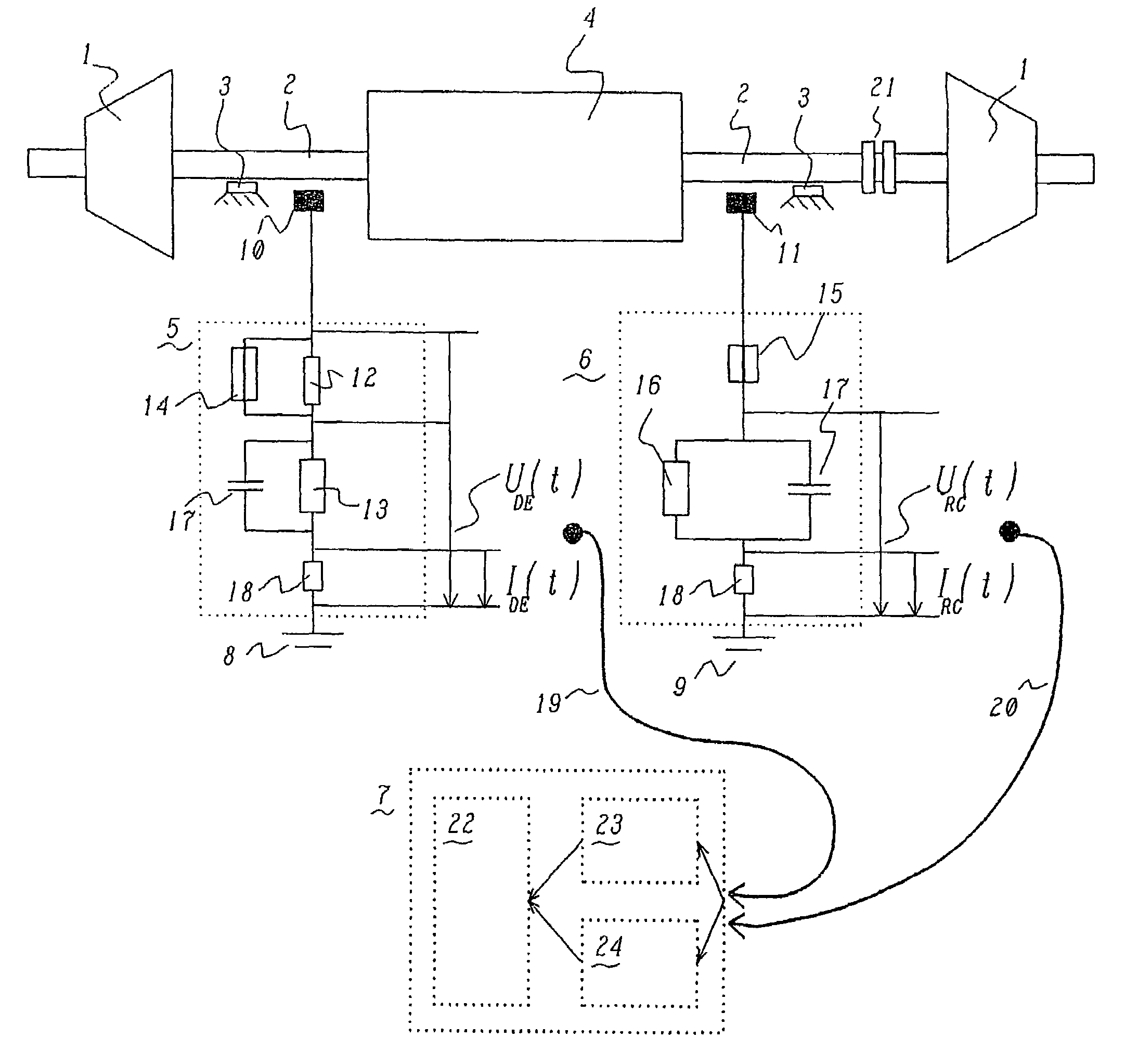
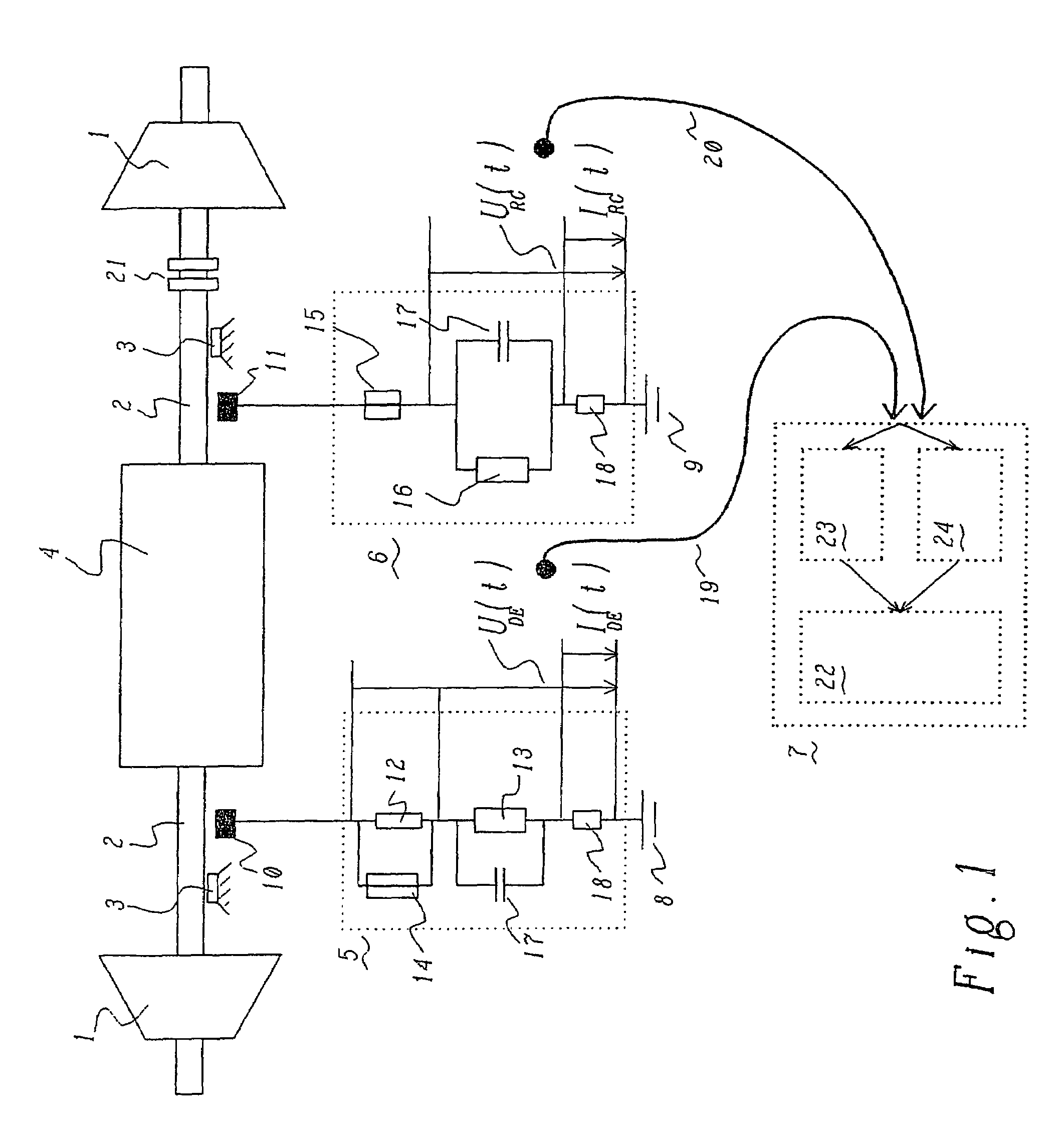
[0033]The FIGURE shows a schematic illustration of a gas turbine installation in which two turbines 1 are arranged at the two ends of a generator 4 as drive means, with the two turbines 1 as well as the generator 4 being arranged in a common shaft 2 or a shaft run. The two turbines should be regarded in this case only as being by way of example, and it is also possible for only one turbine to be arranged there. In order to make it possible to disconnect the generator 4 from the turbines 1, for example for acceleration, conventional couplings are provided and allow the turbines 1 to be mechanically decoupled from the generator 4.

[0034]The shaft 2 is mounted on at least two shaft bearings 3. The oil films in the bearings 3 electrically insulate the shaft 2 from the bearings 3, which are connected to ground. This insulation may, however, collapse in response to voltage spikes above a specific magnitude, and this can lead to electrical erosion problems (spark erosion on the shaft).

[0035...


PUM

PropertyMeasurementUnit
frequenciesaaaaaaaaaa

Abstract

An apparatus and a method for monitoring and / or analysis of electrical machines during operation, wherein the electrical machine has at least one generator with a shaft and drive means for driving this shaft, wherein the shaft is grounded at the first end of the generator, and wherein a measurement unit for measurement of shaft voltage and / or shaft current as a function of time is provided on the shaft at the second end of the generator. An apparatus such as this allows the combined and simultaneous measurement of various fault states by supplying signals for the shaft voltage and / or the shaft current to an analysis unit, wherein the analysis unit allows combined and simultaneous analysis of at least two potential fault states of the electrical machine. Simultaneous cross-relationships between the individual measurement results of individual fault states may be provided so as to allow a clearer and more reliable diagnosis of critical states, not possible when individual phenomena are considered separately.

Description

[0001]This patent application is a continuation for International Patent Application No. PCT / EP2003 / 050611, filed on Sep. 5, 2003, which claims priority to Swiss Patent Application No. CH 2002 1531 / 02, filed on Sep. 10, 2002. The entire disclosure of both applications is incorporated by reference herein.[0002]The present invention relates to an apparatus and a method for monitoring and / or analysis of electrical machines during operation. The electrical machine in this case comprises at least one generator with a shaft and drive means for driving this shaft, wherein the shaft is essentially directly grounded at the first end of the generator, and wherein a measurement unit for measurement of shaft voltage and / or shaft current as a function of time is provided on the shaft at the second end of the generator. This is, in particular, an apparatus for use in power station installations.BACKGROUND[0003]Electrical machines, in particular large electrical machines such as those used in powe...

Claims


Application Information

Patent Timeline
Patent Type & Authority Patents(United States)
IPC IPC(8): G01R31/34G01N29/00G01R31/06G01R31/12H02K7/00
CPCG01R31/1227G01R31/346G01R31/343
Inventor HOBELSBERGER, MAXKIRCHHOFF, INGOPOSEDEL, ZLATIMIR
Owner GENERAL ELECTRIC TECH GMBH
Why Eureka
Try Eureka