Network object cache engine

a network object and cache engine technology, applied in the field of network object cache engines, can solve the problems of large overhead, slow communication path between the server and its clients, and the local operating system and the local file system or file server of the proxy, so as to reduce the amount of available cache, maximize efficiency, and maximize efficiency

Inactive Publication Date: 2006-09-05
CA TECH INC
View PDF60 Cites 49 Cited by
  • Summary
  • Abstract
  • Description
  • Claims
  • Application Information

AI Technical Summary

Benefits of technology

[0009]In a preferred embodiment, the cache engine collects information to be written to disk in write episodes, so as to, maximize efficiency when writing information to disk and so as to maximize efficiency when later reading that information from disk. The cache engine performs write episodes so as to atomically commit changes to disk during each write episode, so the cache engine does not fail in response to loss of power or storage, or other intermediate failure of portions of the cache. The cache engine stores key system objects on each one of a plurality of disks, so as to maintain the cache holographic in the sense that loss of any subset of the disks merely decreases the amount of available cache. The cache engine selects information to be deleted from disk in delete episodes, so as to maximize efficiency when deleting information from disk and so as to maximize efficiency when later writing new information to those areas of disk. The cache engine responds to the addition or deletion of disks as the expansion or contraction of the amount of available cache.

Problems solved by technology

In computer networks for transmitting information, information providers (sometimes called “servers”) are often called upon to transmit the same or similar information to multiple recipients (sometimes called “clients”) or to the same recipient multiple times. This can result in transmitting the same or similar information multiple times, which can tax the communication structure of the network and the resources of the server, and cause clients to suffer from relatively long response times. This problem is especially acute in several situations: (a) where a particular server is, or suddenly becomes, relatively popular; (b) where the information from a particular server is routinely distributed to a relatively large number of clients; (c) where the information from the particular server is relatively time-critical; and (d) where the communication path between the server and its clients, or between the clients and the network, is relatively slow.
While this method achieves the goal of reducing traffic in the network and load on the server, it has the drawback that significant overhead is required by the local operating system and the local file system or file server of the proxy.
This adds to the expense of operating the network and slows down the communication path between the server and the client.
There are several sources of delay, caused primarily by the proxy's surrendering control of its storage to its local operating system and local file system: (a) the proxy is unable to organize the information from the server in its mass storage for most rapid access; and (b) the proxy is unable to delete old network objects received from the servers and store new network objects received from the servers in a manner which optimizes access to mass storage.
In addition to the added expense and delay, the proxy's surrendering control of its storage restricts functionality of the proxy's use of its storage: (a) it is difficult or impossible to add to or subtract from storage allocated to the proxy while the proxy is operating; and (b) the proxy and its local file system cannot recover from loss of any part of its storage without using an expensive redundant storage technique, such as a RAID storage system.

Method used


Image

  • Network object cache engine
  • Network object cache engine
  • Network object cache engine

Examples


Embodiment Construction

[0016]In the following description, a preferred embodiment of the invention is described with regard to preferred process steps and data structures. Those skilled in the art would recognize after perusal of this application that embodiments of the invention can be implemented using general purpose processors and storage devices, special purpose processors and storage devices, or other circuits adapted to particular process steps and data structures described herein, and that implementation of the process steps and data structures described herein would not require undue experimentation or further invention.

Caching Network Objects

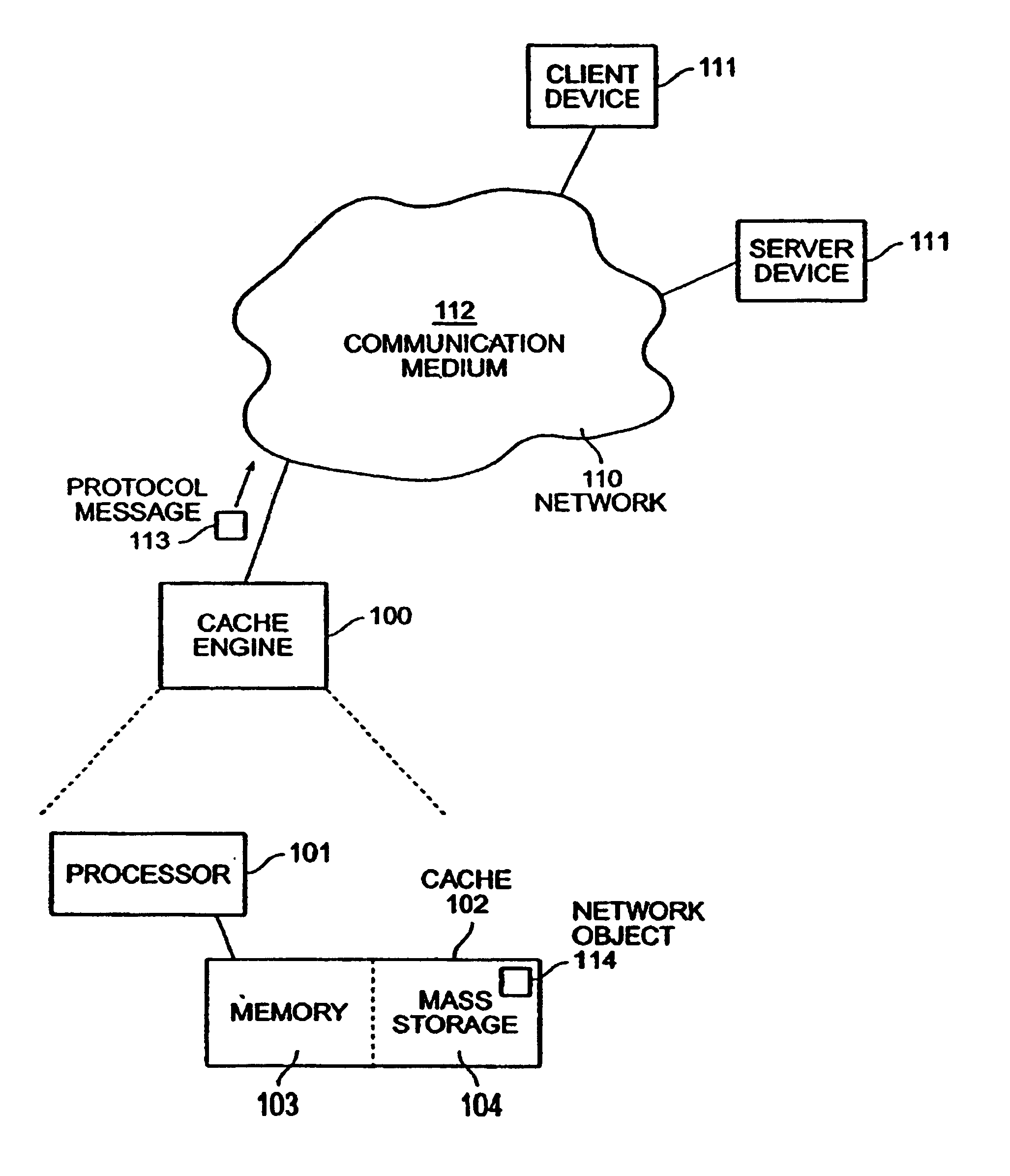
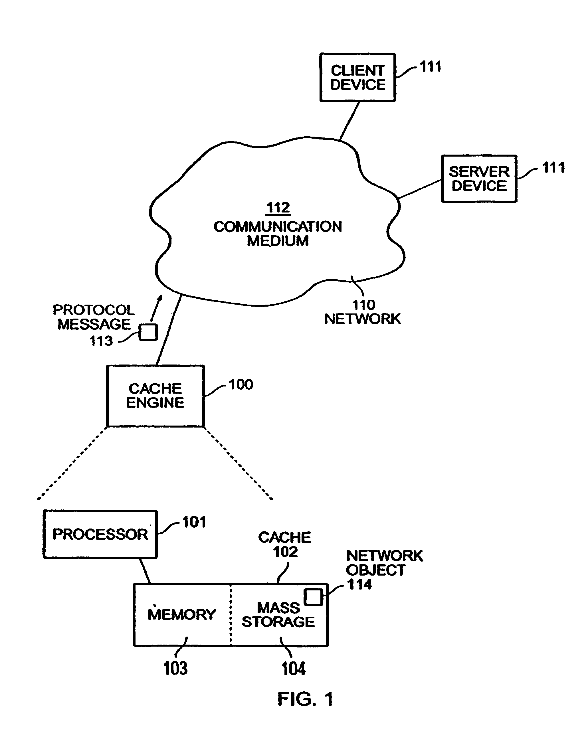
[0017]FIG. 1 shows a block diagram of a network object cache engine in a computer network.

[0018]A cache engine 100 is coupled to a computer network 110, so that the cache engine 100 can receive messages from a set of devices 111 also coupled to the network 110.

[0019]In a preferred embodiment, the network 110 includes a plurality of such devices 111, intercon...


PUM


Abstract

The invention provides a method and system for caching information objects transmitted using a computer network. A cache engine determines directly when and where to store those objects in a memory (such as RAM) and mass storage (such as one or more disk drives), so as to optimally write those objects to mass storage and later read them from mass storage, without having to maintain them persistently. The cache engine actively allocates those objects to memory or to disk, determines where on disk to store those objects, retrieves those objects in response to their network identifiers (such as their URLs), and determines which objects to remove from the cache so as to maintain sufficient operating space. The cache engine collects information to be written to disk in write episodes, so as to maximize efficiency when writing information to disk and so as to maximize efficiency when later reading that information from disk. The cache engine performs write episodes so as to atomically commit changes to disk during each write episode, so the cache engine does not fail in response to loss of power or storage, or other intermediate failure of portions of the cache. The cache engine also stores key system objects on each one of a plurality of disks, so as to maintain the cache holographic in the sense that loss of any subset of the disks merely decreases the amount of available cache. The cache engine also collects information to be deleted from disk in delete episodes, so as to maximize efficiency when deleting information from disk and so as to maximize efficiency when later writing to those areas having former deleted information. The cache engine responds to the addition or deletion of disks as the expansion or contraction of the amount of available cache.

Description

BACKGROUND OF THE INVENTION[0001]1. Field of the Invention[0002]This invention relates to devices for caching objects transmitted using a computer network.[0003]2. Related Art[0004]In computer networks for transmitting information, information providers (sometimes called “servers”) are often called upon to transmit the same or similar information to multiple recipients (sometimes called “clients”) or to the same recipient multiple times. This can result in transmitting the same or similar information multiple times, which can tax the communication structure of the network and the resources of the server, and cause clients to suffer from relatively long response times. This problem is especially acute in several situations: (a) where a particular server is, or suddenly becomes, relatively popular; (b) where the information from a particular server is routinely distributed to a relatively large number of clients; (c) where the information from the particular server is relatively time-...

Claims


Application Information

Patent Timeline
Patent Type & Authority Patents(United States)
IPC IPC(8): G06F11/00G06F11/14G06F12/08G06F17/30
CPCG06F11/1435G06F17/30902G06F12/0813G06F16/9574
Inventor MALCOLM, MICHAELZARNKE, ROBERT
Owner CA TECH INC
Why Eureka
Try Eureka