Cylindrical vibration damping device
a technology of vibration damping and cylindrical shaft, which is applied in the direction of spring/damper functional characteristics, shock absorption, machine supports, etc., can solve the problems of reducing the elastic recovery force of the resin outer shell, reducing the elastic recovery force, and reducing the elastic recovery. , to achieve the effect of high stability and resistance to dislodging of the rubber bushing
- Summary
- Abstract
- Description
- Claims
- Application Information
AI Technical Summary
Benefits of technology
Problems solved by technology
Method used
Image

Examples
first embodiment
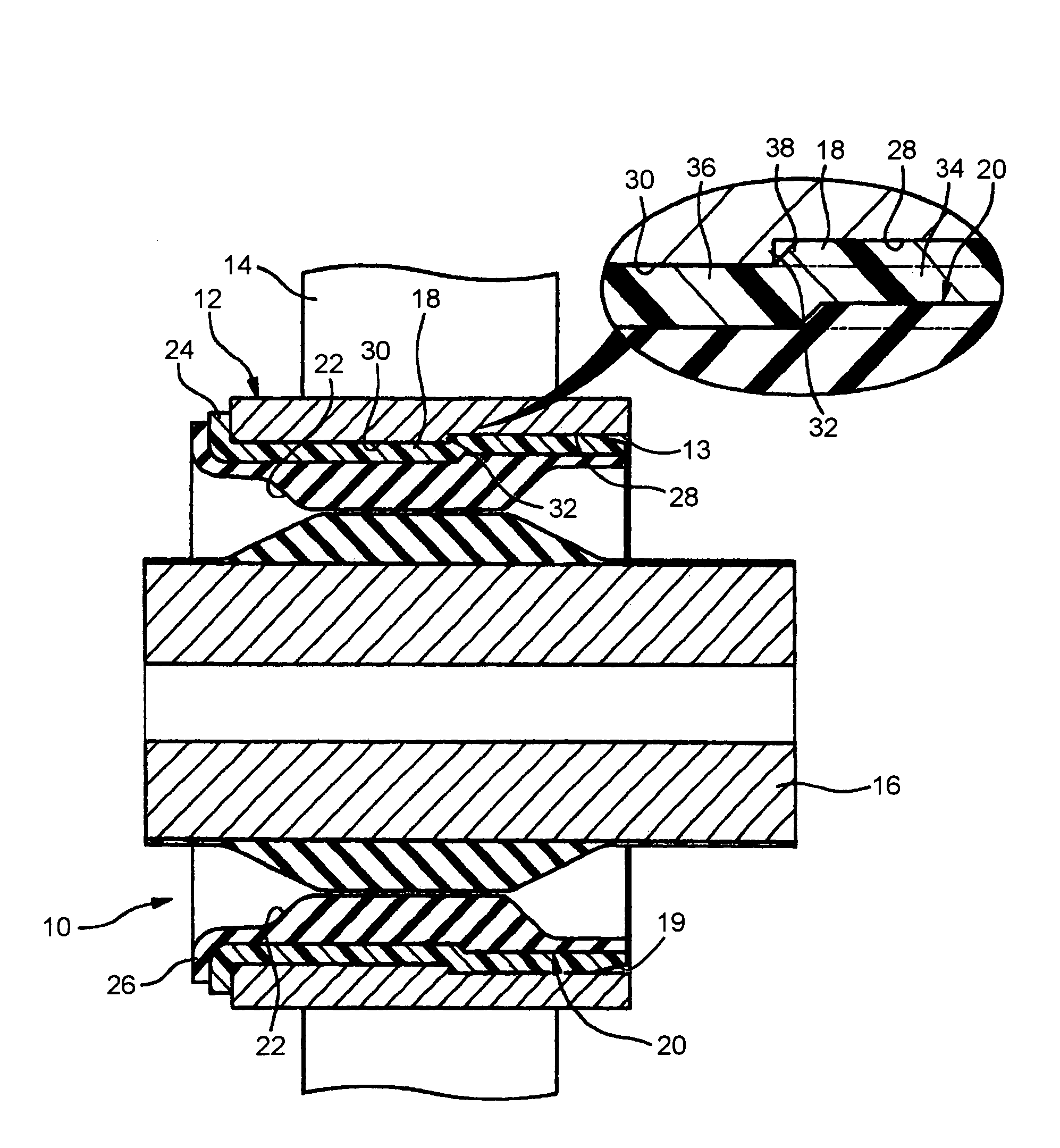
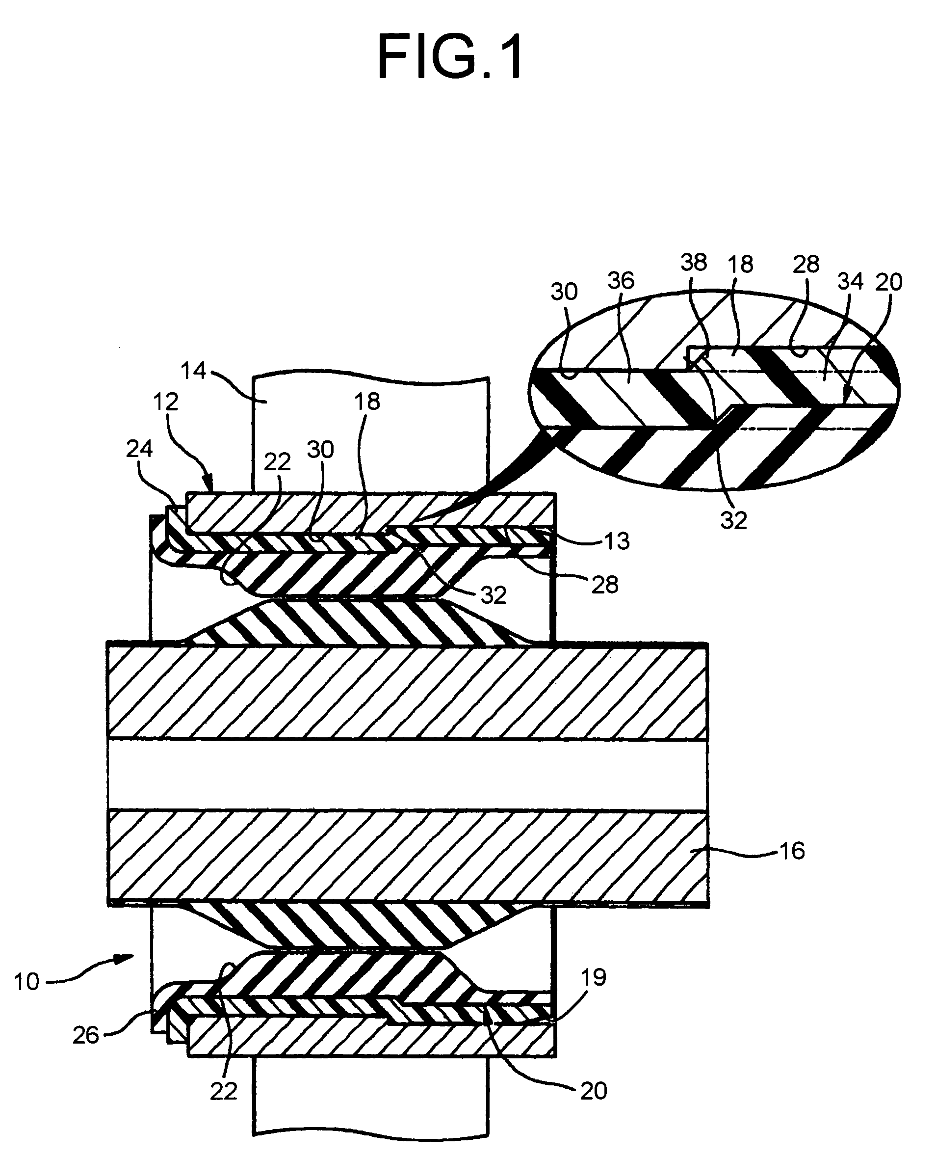
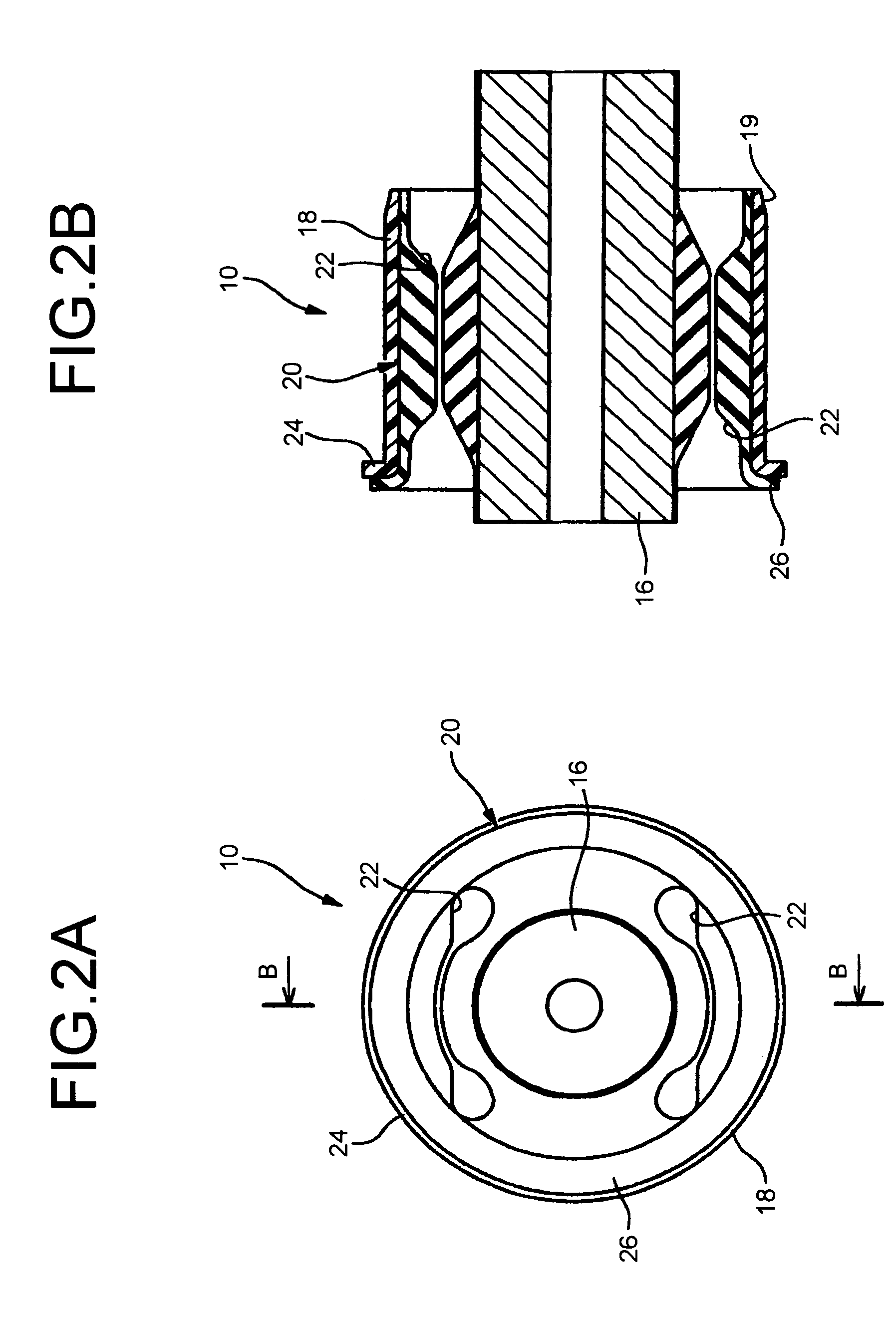
[0063]Referring first to FIGS. 1–4, there is shown a cylindrical vibration-damping device constructed according to the present invention. The present cylindrical vibration-damping device may be applied to a linking portion to link a trailing arm to a vehicle body in a torsion beam type rear suspension of an automotive vehicle. FIG. 2 shows a rubber bushing 10 of the cylindrical vibration-damping device, and
[0064]FIG. 3 shows a mounting member 12 into which the rubber bushing 10 will be press fit. FIG. 1 shows the rubber bushing 10 of FIG. 2 assembled press fit into the mounting member 12 of FIG. 3. In FIG. 1, 14 denotes an arm extending out from the mounting member 12.
[0065]As shown in FIG. 2, the rubber bushing 10 has an inner sleeve 16 of cylindrical shape, an outer sleeve 18 similarly of cylindrical shape, and a rubber elastic body 20 interposed between and elastically connecting the inner and outer sleeves 16, 18. This rubber elastic body 20 is integrally bonded to the inner and...
second embodiment
[0095] the outer sleeve 68 as well as the elastic body 70 do not have flange portions at their axial ends, as shown in FIG. 12. That is, the rubber bushing 60 is of flangeless type, and axially opposite end portions 19 thereof have the tapered outer surface configuration.
[0096]As is apparent from FIG. 14, the rubber bushing 60 has an outside diameter d1 of 67 mm, and has an axial length l1 that is approximately equal to an axial length L1 of a mounting member 62.
[0097]A variety of resin including a thermoplastic resin and heat-setting resin may be usable for fabricating the outer sleeve 68, like in the first embodiment.
[0098]On the other hand, the mounting member 62 has an overall cylindrical shape with a cylindrical bore 63 whose profile appropriately corresponds to that of the rubber bushing 60, as shown in FIGS. 13A and 13B. The mounting member 62 is made entirety of metal.
[0099]Onto the cylindrical bore 63 of the mounting member 62 are formed a pair of recessed portions 28 reces...
third embodiment
[0109]Referring next to FIGS. 15–17, there is shown a cylindrical vibration damping device constructed according to the present invention. The present cylindrical vibration-damping device may be applied to a linking portion to link a trailing arm to a vehicle body in a torsion beam type rear suspension of an automotive vehicle. FIG. 16 shows a rubber bushing 110 of the cylindrical vibration-damping device, and FIG. 17 shows a mounting member 112 having a cylindrical bore 113 into which the rubber bushing 110 will be press fitted. FIG. 15 shows the rubber bushing 110 of FIG. 16 assembled press fit into the mounting member 112 of FIG. 17. In FIG. 15, 114 denotes an arm extending out from the mounting member 112.
[0110]As shown in FIG. 17, the mounting member 112 has an overall cylindrical shape with the cylindrical bore 113 whose profile appropriately corresponds to that of the rubber bushing 110. The mounting member 112 is made entirety of metal. Onto the inner surface of the mounting...
PUM
 Abstract
Description
Claims
Application Information
 - R&D
- Intellectual Property
- Life Sciences
- Materials
- Tech Scout
- Unparalleled Data Quality
- Higher Quality Content
- 60% Fewer Hallucinations
Browse by: Latest US Patents, China's latest patents, Technical Efficacy Thesaurus, Application Domain, Technology Topic, Popular Technical Reports.
© 2025 PatSnap. All rights reserved.Legal|Privacy policy|Modern Slavery Act Transparency Statement|Sitemap|About US| Contact US: help@patsnap.com