Bearing device
a technology of bearing device and bearing body, which is applied in the direction of bearing unit rigid support, manufacturing tools, transportation and packaging, etc., can solve the problem of not being able to confirm from the appearance whether or not the floating state has occurred, and achieve the effect of improving the coming-out resistan
- Summary
- Abstract
- Description
- Claims
- Application Information
AI Technical Summary
Benefits of technology
Problems solved by technology
Method used
Image
Examples
second embodiment
OF THE INVENTION
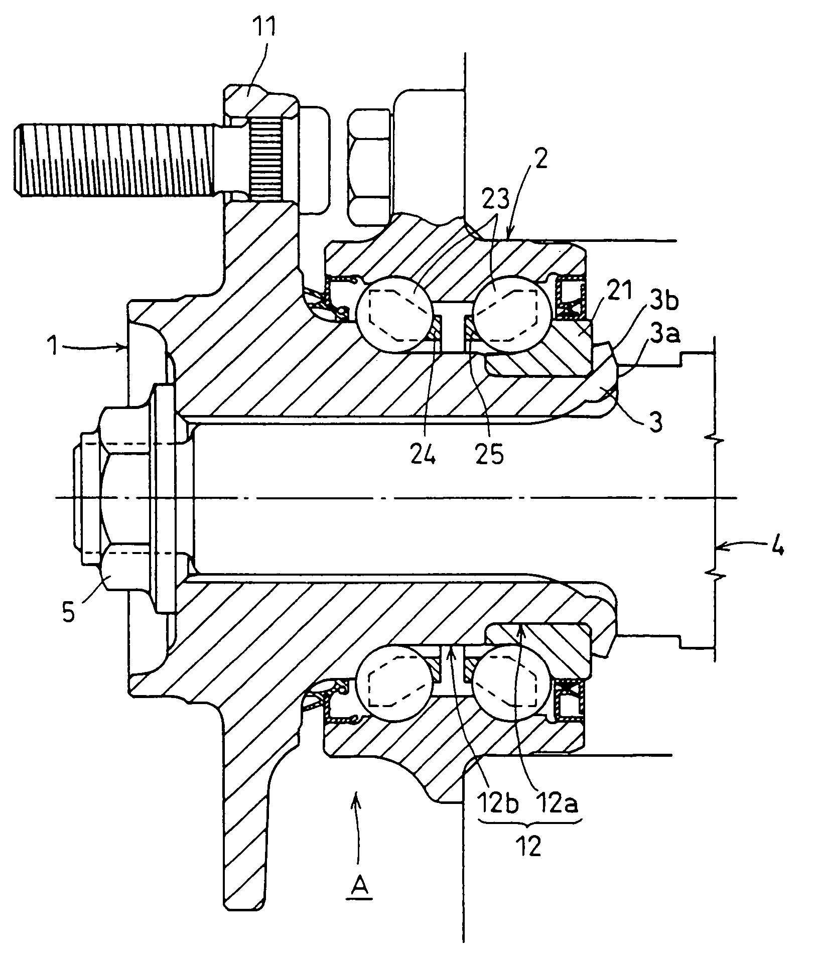
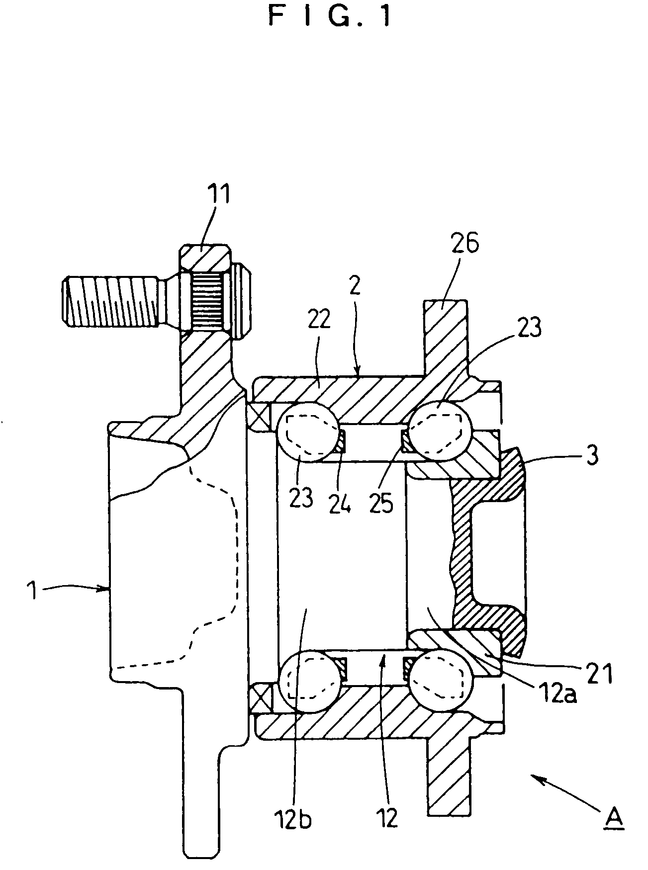
[0056]A second preferred embodiment of the invention will be described with reference to FIGS. 6 to 8. The hub unit A to be exemplified in this second embodiment is of the type to be used with the drive wheels of a vehicle and is interposed between a drive shaft 4 and a shaft case 5 of the vehicle. Specifically, the journal 12 of the hub wheel 1 is attached to the drive shaft 4, and the outer ring 22 of the bearing 2 is attached to the shaft case 5. In more detail, the journal 12 of the hub wheel 1 is splined to the drive shaft 4 and coupled to the same by using a nut 6, and the outer ring 22 is coupled at its flange 26 to the shaft case 5 by using bolts 7.
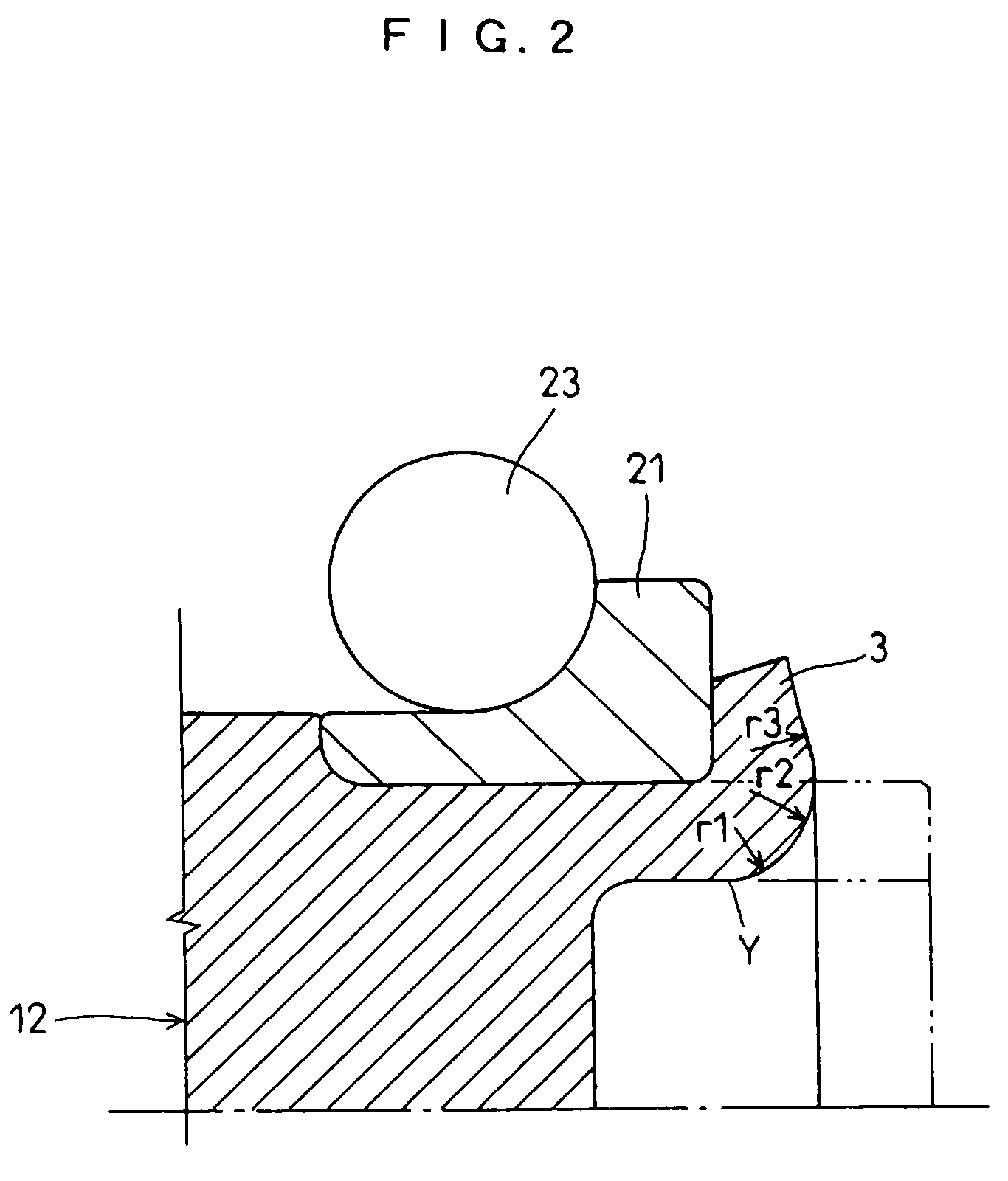
[0057]In this second embodiment, the caulked portion 3 to be formed at the journal 12 of the hub wheel 1 has a radial flat face 3a formed at a radially intermediate portion W of its outer end face. This flat face 3a is formed into an annular shape. In this caulked portion 3, the radially inner region and the radial...
third embodiment
OF THE INVENTION
[0065]A third preferred embodiment of the invention will be described with reference to FIGS. 9 to 11. In this third embodiment, the flat face 3a is formed in the radially intermediate region at the outer end face of the caulked portion 3, and a tapered face 3b sloped at a predetermined angle θ with respect to a virtual plane in the radial direction is formed on the radially outer region of the flat face 3a.
[0066]In order to form this caulked portion 3, a rolling-caulking treatment is performed at first as in the foregoing second embodiment. As shown in FIG. 19 according to the prior art, more specifically, the caulking jig 90 is applied at its leading end to the cylindrical portion 12c of the journal 12 and is rolled at the predetermined angle α on the single-dotted line O. As a result, the cylindrical portion 12c of the journal 12 is bent radially outward to form the roundish caulked portion 3, as shown in FIG. 11A. After this, a shaping press jig 200 is applied t...
fourth embodiment
OF THE INVENTION
[0068]A fourth preferred embodiment of the invention will be described with reference to FIGS. 12 to 14. In this fourth embodiment, the flat face 3a is formed in the radially outer region at the outer end face of the caulked portion 3.
[0069]In order to form this caulked portion 3, a rolling-caulking treatment is performed at first as in the foregoing second embodiment. As shown in FIG. 19 according to the prior art, more specifically, the caulking jig 90 is applied at its leading end to the cylindrical portion 12c of the journal 12 and is rolled at the predetermined angle α on the single-dotted line O. As a result, the cylindrical portion 12c of the journal 12 is bent radially outward to form the roundish caulked portion 3, as shown in FIG. 14A. After this, a shaping press jig 300 is applied to the caulked portion 3, as shown in FIG. 14B, to press the outer end face of the caulked portion 3 under a predetermined pressure to form the flat face 3a on the radially outer...
PUM
| Property | Measurement | Unit |
|---|---|---|
| angle | aaaaa | aaaaa |
| contact angles | aaaaa | aaaaa |
| radius of curvature r0 | aaaaa | aaaaa |
Abstract
Description
Claims
Application Information
 - R&D
- Intellectual Property
- Life Sciences
- Materials
- Tech Scout
- Unparalleled Data Quality
- Higher Quality Content
- 60% Fewer Hallucinations
Browse by: Latest US Patents, China's latest patents, Technical Efficacy Thesaurus, Application Domain, Technology Topic, Popular Technical Reports.
© 2025 PatSnap. All rights reserved.Legal|Privacy policy|Modern Slavery Act Transparency Statement|Sitemap|About US| Contact US: help@patsnap.com


