
A kind of grinding roller sleeve and its manufacturing method

A manufacturing method and technology of grinding rollers, which are applied in the direction of manufacturing tools, casting molding equipment, casting mold components, etc., can solve the problems of small dispersion of ceramic particles, interface debonding, and large wear surface area occupied by wear-resistant materials of coal mill grinding rollers. The problem of uniform distribution of shedding ceramic particles can achieve the effect of large wear surface area, ensuring firmness, and improving the performance of shear resistance and shedding resistance

Active Publication Date: 2021-03-23
上海电气上重碾磨特装设备有限公司
View PDF7 Cites 0 Cited by
  • Summary
  • Abstract
  • Description
  • Claims
  • Application Information

AI Technical Summary

Problems solved by technology

This method improves many problems such as incomplete penetration and small dispersion of ceramic particles caused by traditional gravity casting. However, due to the large difference in density between ceramic particles and iron-based metal melt, ceramic particles can only be suspended on the surface of the metal melt. , interfacial wetting reaction is not easy to occur, so there are still defects such as interfacial debonding, particle shedding, etc.
[0008] To sum up, the existing manufacturing methods of various ceramic-metal composite grinding roller sleeves have some problems, which cannot meet the requirements of large wear surface area, anti-shedding, and uniform distribution of ceramic particles for coal mill grinding rollers. Requirements, in order to solve this kind of defect, it is necessary to carry out effective innovation on the existing technology

Method used


Image

  • A kind of grinding roller sleeve and its manufacturing method
  • A kind of grinding roller sleeve and its manufacturing method
  • A kind of grinding roller sleeve and its manufacturing method

Examples


Embodiment Construction

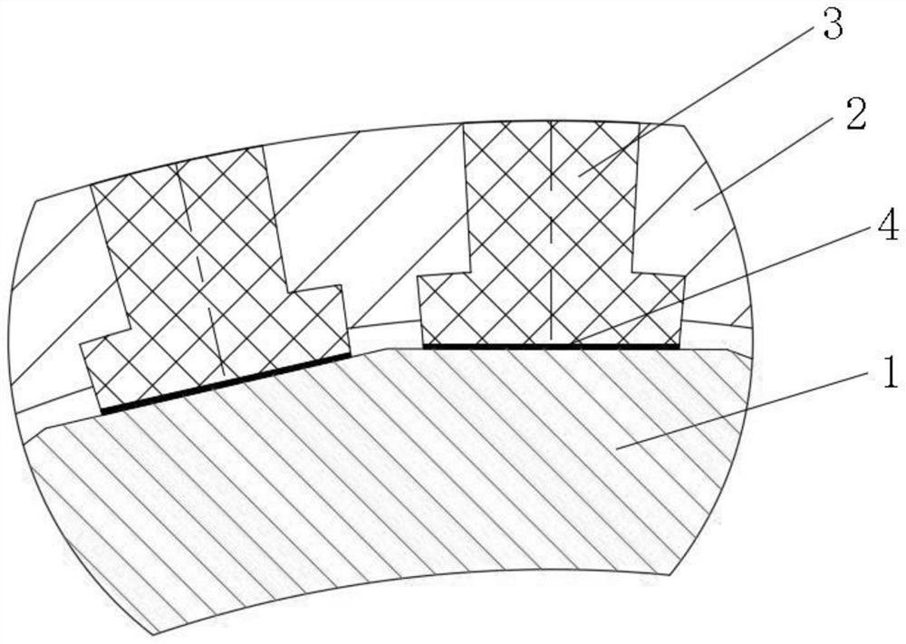
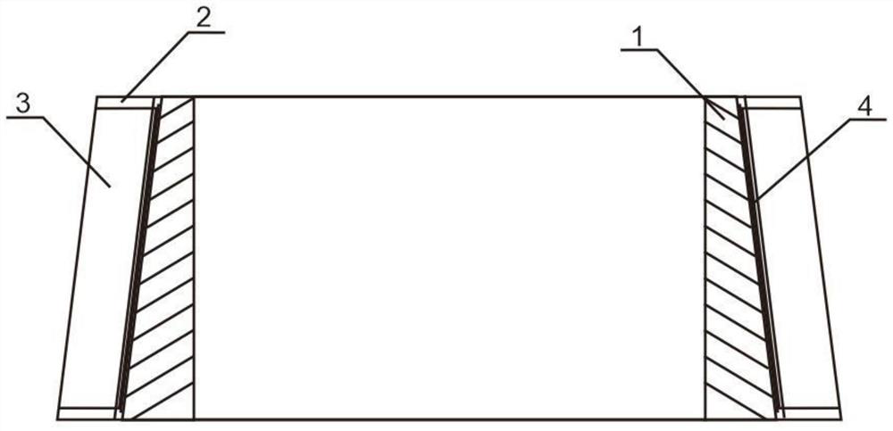
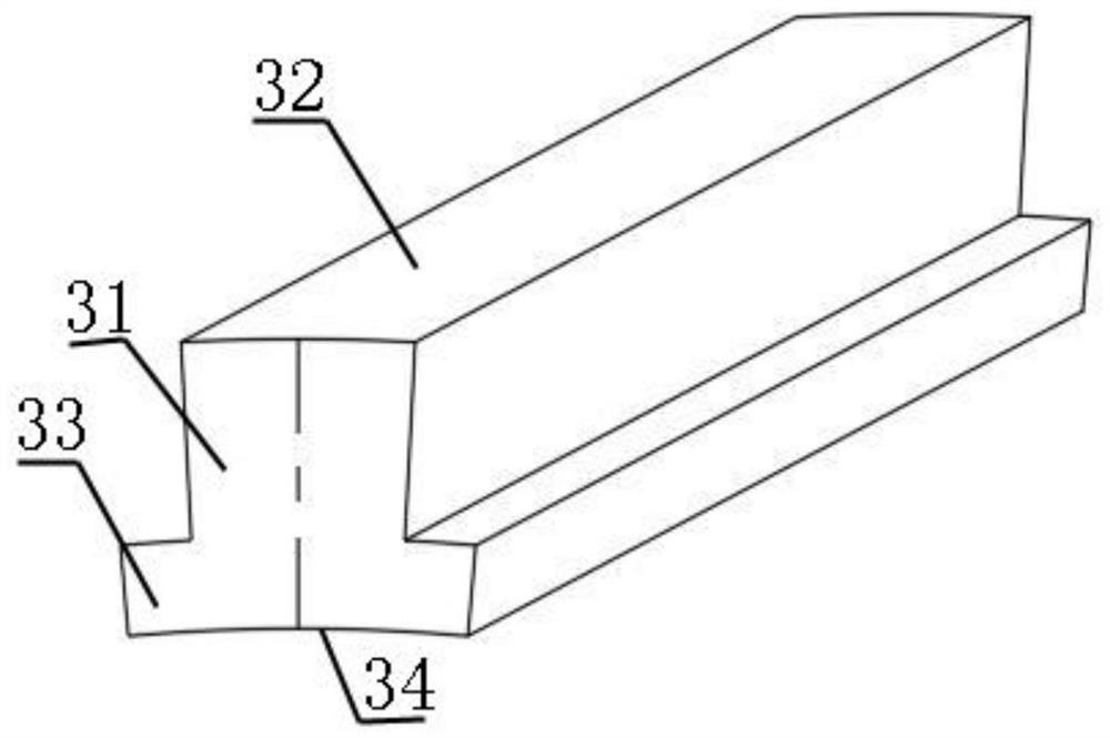
[0035] Such as Figure 1-4 As shown, in one embodiment of the present invention, the grinding roll sleeve includes a grinding roll core 1, a metal roll sleeve 2, a cermet block 3 and an adjusting gasket 4;

[0036] In the axial direction, the cross-sections of the grinding roller core 1 and the metal roller sleeve 2 are both hollow circular platform structures, and the hollow structure of the grinding roller core 1 is cylindrical, because the metal roller sleeve 2 needs to be placed outside the grinding roller core 1 circumference, and the axial direction of the grinding roller core 1 is in the shape of a truncated cone. Therefore, the hollow structure of the metal roller sleeve 2 is also in the shape of a truncated cone. There is a taper in its axial direction, that is, one end is larger than the other end, and the taper of the outer surface of the grinding roller core 1 is the same as the taper of the inner surface and the outer surface of the metal roller sleeve 2;

[0037...


PUM

PropertyMeasurementUnit
lengthaaaaaaaaaa
widthaaaaaaaaaa
thicknessaaaaaaaaaa

Abstract

The invention relates to a grinding roller sleeve and a manufacturing method thereof. The grinding roller sleeve comprises a grinding roller core, a metal roller sleeve, metal ceramic blocks and adjusting gaskets, wherein the axial sections of the grinding roller core and the metal roller sleeve are of hollow circular truncated cone structures; the grinding roller core is arranged on the inner side of the metal roller sleeve; a plurality of embedding grooves are uniformly formed in the metal roller sleeve at intervals; the metal ceramic blocks matched with the embedding grooves in shape and size are embedded into the embedding grooves respectively; the adjusting gaskets are inserted into gaps between the metal ceramic blocks and the grinding roller core; and the abutting condition of the metal ceramic blocks and the grinding roller core is adjusted through the adjusting gaskets. The grinding roller sleeve is obtained in a mechanical combination mode; a wear-resistant material of the grinding roller sleeve occupies a large wear surface area, and is anti-falling; ceramic particles are uniformly distributed; and the defects of a grinding roller sleeve manufactured through a method inthe prior art are effectively overcome.

Description

technical field [0001] The invention relates to the field of coal pulverizers, in particular to a grinding roller sleeve for a coal pulverizer and a manufacturing method thereof. Background technique [0002] Coal mill grinding roller sleeves are key vulnerable parts in power plant pulverizing equipment. Because of their harsh operating environment, their service life is generally short. In order to improve the service life of coal mill grinding roller sleeves, cermets are now mostly used as roller sleeves. Wear-resistant material. [0003] The manufacturing methods of existing metal-ceramic composite grinding roller sleeves for coal mills include: [0004] 1) A prefabricated ceramic-metal matrix composite material is used to manufacture the grinding roller sleeve. In this method, a strip-shaped metal wear-resistant plate with good toughness but low hardness is used as the substrate, and holes are drilled on the metal wear-resistant plate (such as a steel plate), and then ...

Claims


Application Information

Patent Timeline
Patent Type & Authority Patents(China)
IPC IPC(8): B02C4/30B22C9/02B22C9/28B23P15/00
CPCB02C4/305B22C9/02B22C9/28B23P15/00
Inventor 沈光明李志强蒋理想高梦珂吴正华周钢群王杰楼慧卉
Owner 上海电气上重碾磨特装设备有限公司
Learn More