Peristaltic micropump

a micropump and micro-pump technology, applied in the field of micropump, can solve the problems of high cost of segmented piezo-bending elements, inability to self-prime and bubble-tolerant pumps, and difficulty in construction, so as to achieve bubble-tolerant self-priming operation and easy construction

Active Publication Date: 2006-09-12
FRAUNHOFER GESELLSCHAFT ZUR FOERDERUNG DER ANGEWANDTEN FORSCHUNG EV
View PDF8 Cites 43 Cited by
  • Summary
  • Abstract
  • Description
  • Claims
  • Application Information

AI Technical Summary

Benefits of technology

[0012]It is the object of the present invention to provide a peristaltic micromembrane pump which is easily constructed and which enables a bubble-tolerant self-priming operation.

Problems solved by technology

The ceramic layer has to be polarized in a segmented manner, which is technically difficult.
Such a segmented piezo-bending element thus is expensive and allows only small stroke volumes, so that such a pump cannot work in a bubble-tolerant and self-priming manner.
Alternatively, the realization of pneumatic drives would be possible, which, however, necessitates high expenditure regarding external pneumatics as well as the switching valves required for this. decreased by moving the second membrane region also towards the pump body.
Alternatively, according to the invention, so-called piezo-stacks may also be used as piezo-actors, which are, however, disadvantageous as opposed to piezo-membrane converters in that they are large and expensive, provide problems with respect to the connection technique between stack and membrane and problems with the adjustment of the stacks, and are thus all in all connected with higher expenditure.
This Pneumatic drives thus represent expensive, costly and space-intensive methods to implement membrane deflection.

Method used


Image

  • Peristaltic micropump
  • Peristaltic micropump
  • Peristaltic micropump

Examples


Embodiment Construction

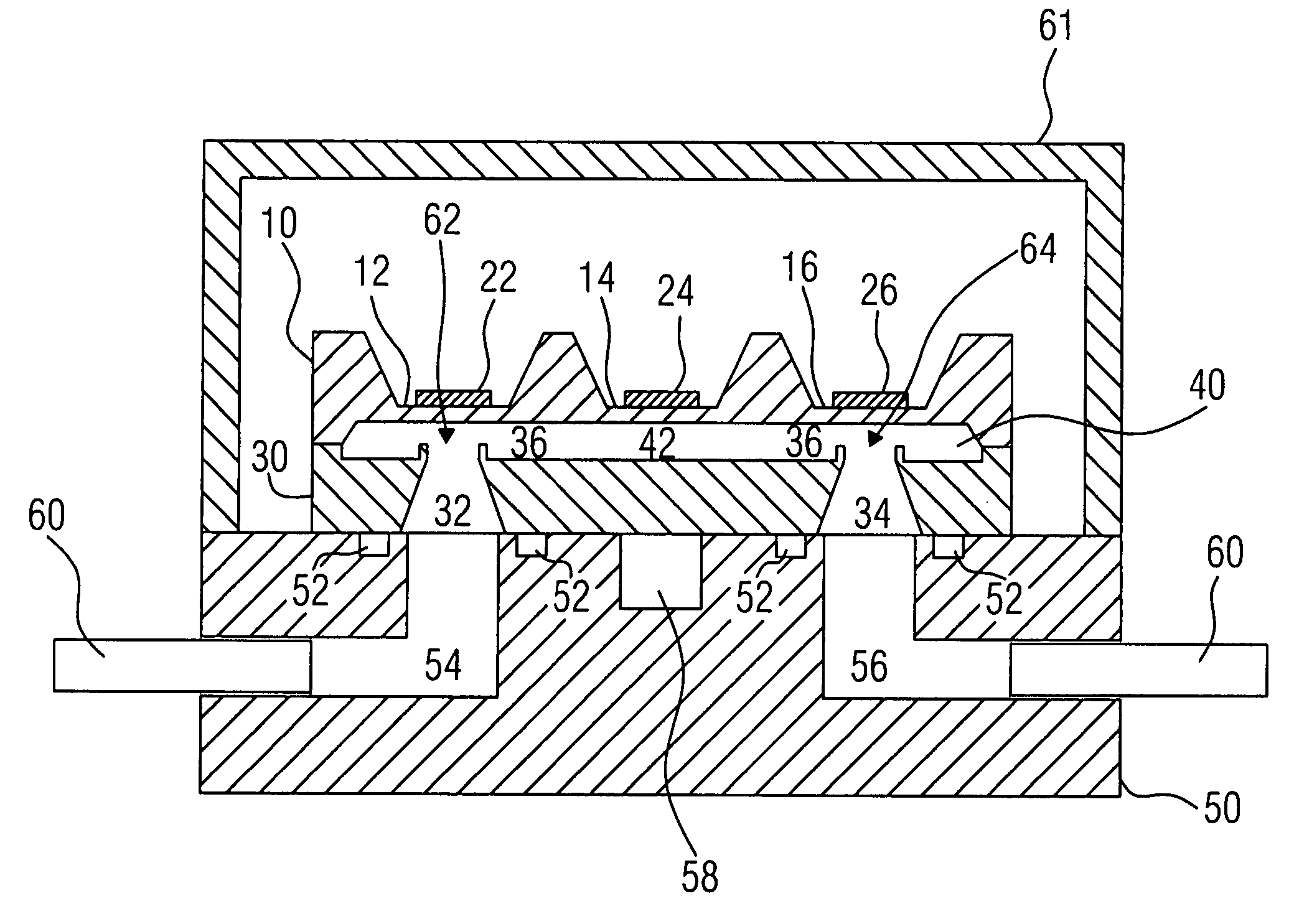
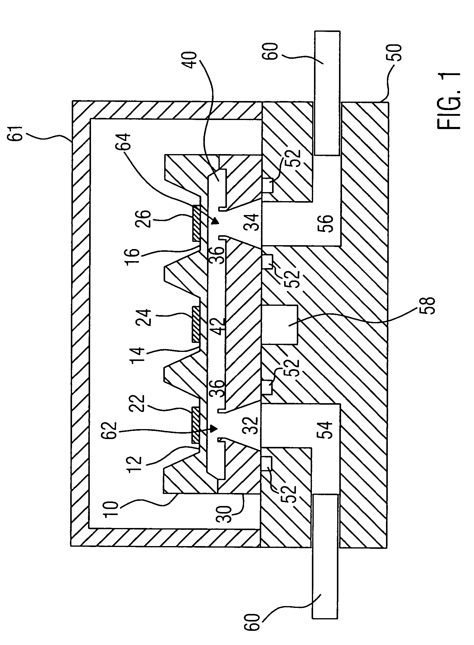
[0032]A first embodiment of an inventive peristaltic micropump integrated in a fluid system is shown in FIG. 1. The micromembrane pump includes a membrane element 10 having three membrane sections 12, 14, and 16. Each of the membrane sections 12, 14, and 16 is provided with a piezo-element 22, 24, and 26, respectively, and forms a piezo-membrane converter together therewith. The piezo-elements 22, 24, 26 may be glued on the respective membrane sections or may be formed on the membrane by a screen print or other thick film techniques.

[0033]The membrane element is circumferentially joint to a pump body 30 at outer regions thereof, so that there is a fluid-tight connection between them. In the pump body 30 two fluid passages 32 and 34 are formed, one of which, according to pumping direction, represents a fluid inlet and the other a fluid outlet. In the embodiment shown in FIG. 1, the fluid passages 32, 34 are each surrounded by a sealing lip 36.

[0034]Furthermore, in the embodiment show...


PUM


Abstract

A Peristaltic micropump includes a first membrane region with a first piezo-actor for actuating the first membrane region, a second membrane region with a second piezo-actor for actuating a second membrane region, and a third membrane region with a third piezo-actor for actuating the third membrane region. A pump body forms, together with the first membrane region, a first valve whose passage opening is open in the non-actuated state of the first membrane region and whose passage opening may be closed by actuating the first membrane region. The pump body forms, together with the second membrane region, a pumping chamber whose volume may be decreased by actuating the second membrane region. The pump body forms, together with the third membrane region, a second valve whose passage opening is open in the non-actuated state of the third membrane region and whose passage opening may be closed by actuating the third membrane region. The first and the second valve are fluidically connected to the pumping chamber.

Description

CROSS-REFERENCE TO RELATED APPLICATION[0001]This application is a continuation of co-pending International Application No. PCT / EP03 / 09352, filed Aug. 22, 2003, which designated the United States and was not published in English and is incorporated herein by reference in its entirety.BACKGROUND OF THE INVENTION[0002]1. Field of the Invention[0003]The present invention relates to a micropump, and in particular a micropump working according to a peristaltic pumping principle.[0004]2. Description of the Related Art[0005]Micropumps working according to a peristaltic pumping principle are known from the prior art. The article “Design and simulation of an implantable medical drug delivery system using microelectromechanical systems technology”, by Li Cao et al., Sensors and Actuators, A94 (2001), pages 117 to 125, deals with a peristaltic micropump comprising an inlet, three pumping chambers, three silicon membranes, three normally closed active valves, three piezo-stack actuators of PZT, ...

Claims


Application Information

Patent Timeline
Patent Type & Authority Patents(United States)
IPC IPC(8): F04B17/00F04B43/02F04B43/04
CPCF04B43/046F04B43/043F04B43/14
Inventor RICHTER, MARTINWACKERLE, MARTINCONGAR, YUCELNISSEN, JULIA
Owner FRAUNHOFER GESELLSCHAFT ZUR FOERDERUNG DER ANGEWANDTEN FORSCHUNG EV
Why Eureka
Try Eureka