Fluid tank

a technology of fluid tank and slurry, which is applied in the direction of liquid degasification, water/sewage treatment by degassing, and separation processes, etc. it can solve the problems of affecting the operation affecting the efficiency of the fluid tank, and affecting the quality so as to reduce the cost of the fluid tank, and enhance the strength

Inactive Publication Date: 2006-09-12
KOMATSU LTD
View PDF26 Cites 23 Cited by
  • Summary
  • Abstract
  • Description
  • Claims
  • Application Information

AI Technical Summary

Benefits of technology

[0041]To the contrary, with a fluid tank according to the invention, the pump operates properly without cavitation even at a high land where the atmospheric pressure is low because the bubble removing device effectively removes bubbles. Thus, unlike conventional fluid tanks, the provision of a pressurizing device is not necessary and hence the fluid tank does not need to have an enhanced strength to make it possible to reduce the cost of the fluid tank. Additionally, the fluid tank does not require space for installing a pressurizing device so that the system comprising the fluid tank can be made remarkably compact.
[0042]Furthermore, when a fluid tank according to the invention is provided with a breat...

Problems solved by technology

If bubbles exist in hydraulic fluid, a phenomenon called cavitation can take place to damage the pump.
However, all the above listed types are accompanied by problems specific to each of them.
Since a bubble removing device of the first type is arranged outside the hydraulic tank, it requires a large space dedicated to the hydraulic system because a bubble removing device has to be installed...

Method used


Image

  • Fluid tank
  • Fluid tank
  • Fluid tank

Examples


1st embodiment

[1st Embodiment]

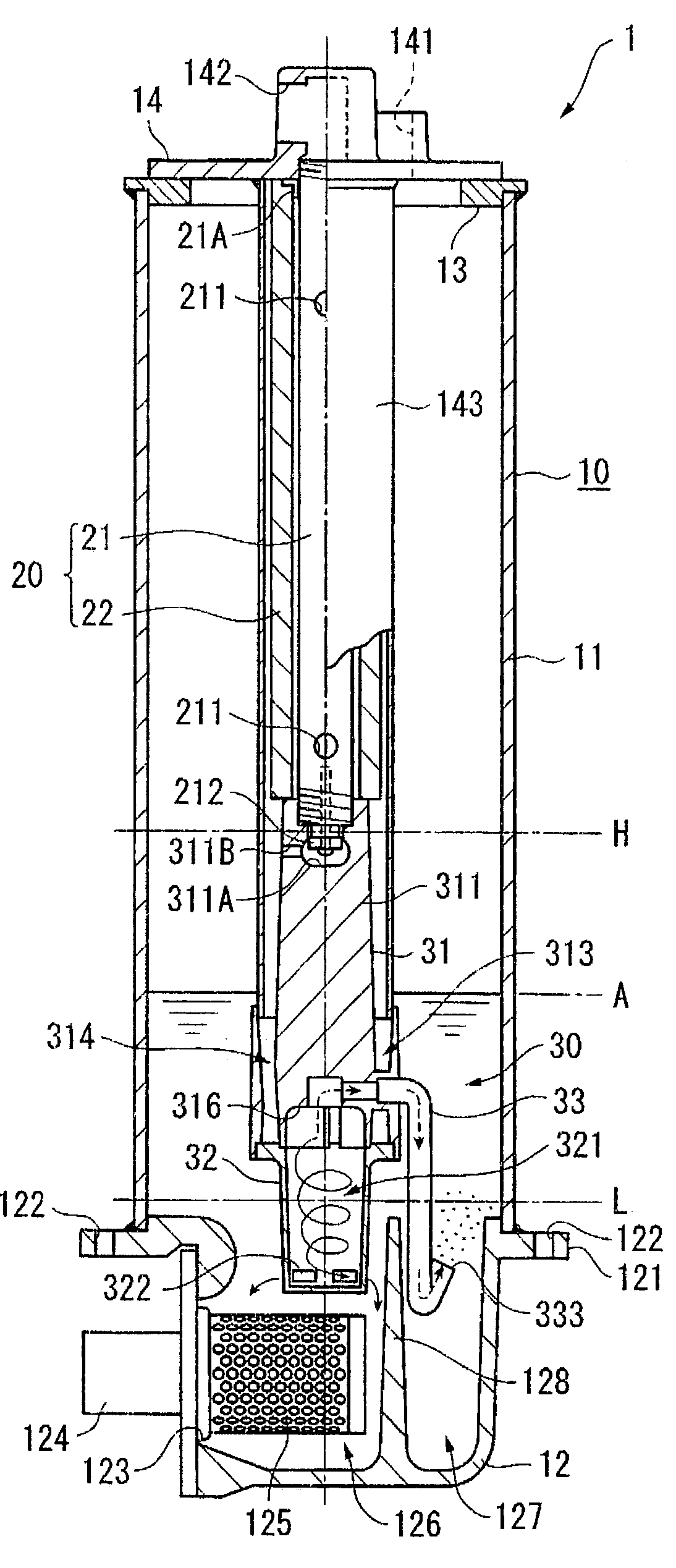
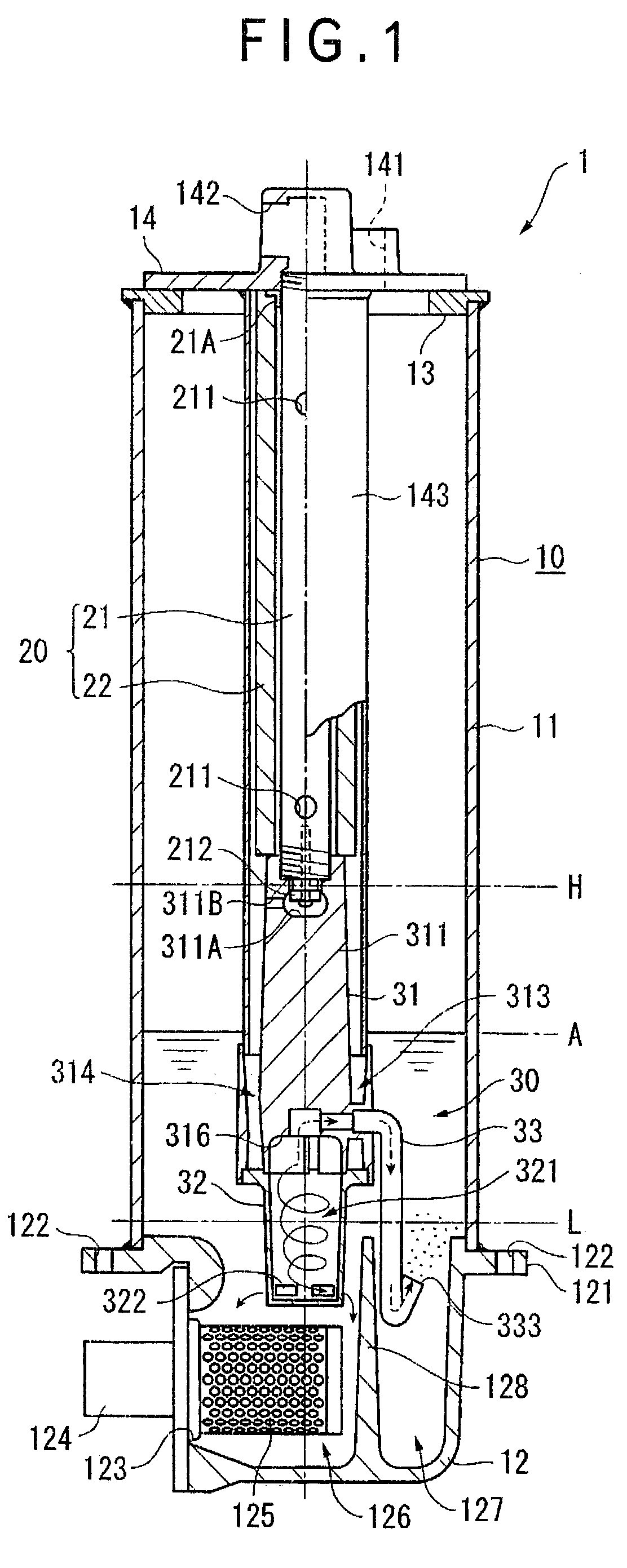
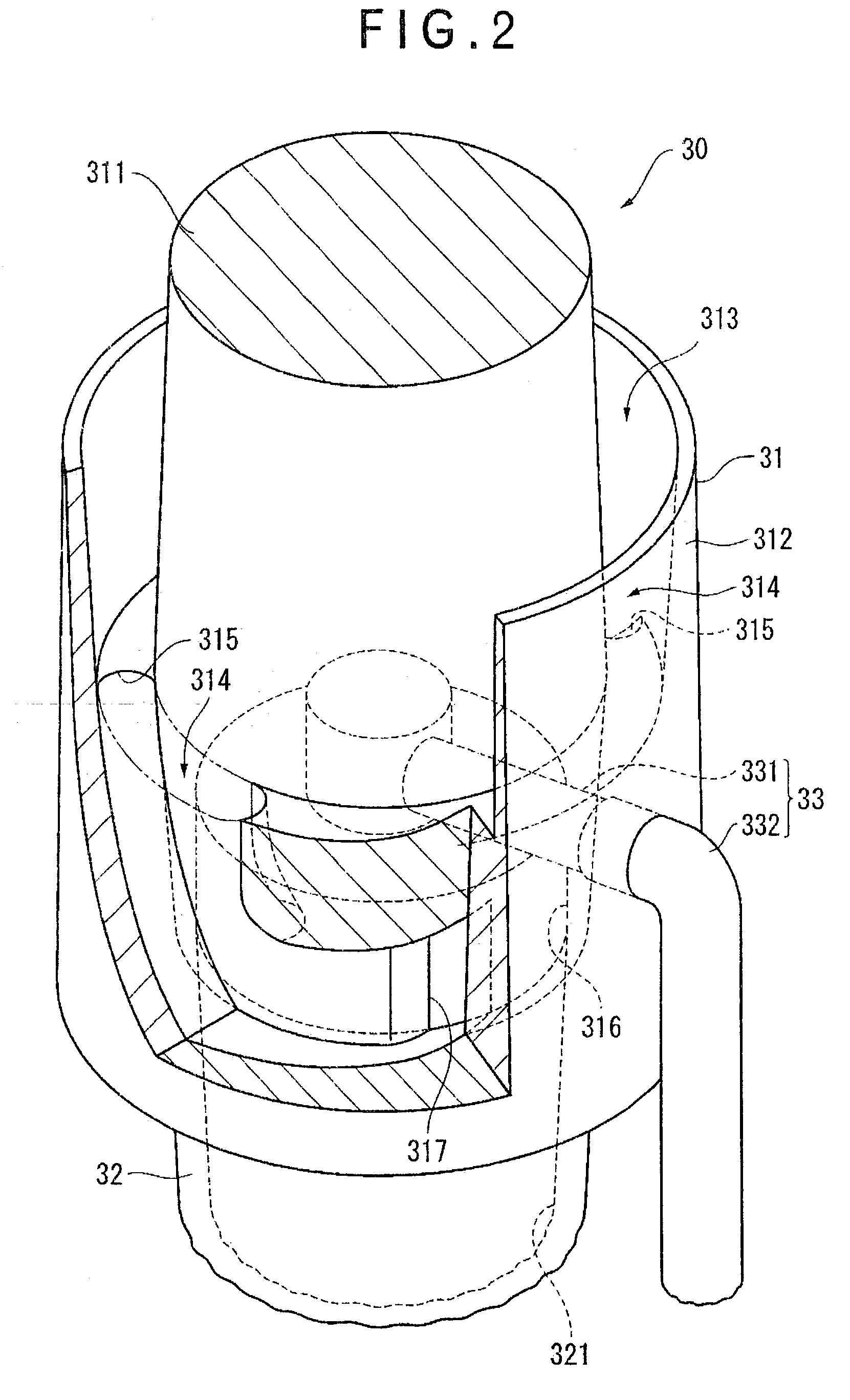
[0058]FIG. 1 is a schematic cross sectional front view of the first embodiment of hydraulic tank (fluid tank) 1 according to the invention and FIG. 2 is a schematic partial cross sectional perspective view of a principal part of the bubble removing device 30 arranged in the hydraulic tank 1 of FIG. 1.

[0059]The hydraulic tank 1 may typically be fitted to a construction machine so as to be used to contain hydraulic fluid (fluid) for driving the working equipment. In other words, the hydraulic tank 1 is connected to a control valve (not shown), a cylinder that operates as part of the working equipment, an oil cooler and so on as well as to a pump (not shown) by way of respective hydraulic fluid flow paths to establish a hydraulic circuit and a hydraulic system.

[0060]The hydraulic tank 1 comprises a tank main body 10, a filter 20 contained in the tank main body 10 and a bubble removing device 30 also contained in the tank main body 10, the filter 20 and the bubble removi...


PUM

PropertyMeasurementUnit
Momentumaaaaaaaaaa
Pressureaaaaaaaaaa

Abstract

A fluid tank fluid is provided which includes a bubble removing device provided therein to remove bubbles from the fluid. The bubble removing device includes a cyclone chamber for generating a swirling current in the fluid flowing therethrough to separate bubbles from the fluid. At least one outflow port is provided through which the fluid from which the bubbles have been separated flows from the cyclone chamber. And an exhaust port is provided through which the bubbles separated from the fluid are driven from the cyclone chamber.

Description

BACKGROUND OF THE INVENTION[0001]1. Field of the Invention[0002]The present invention relates to a fluid tank and, more particularly, it relates to a fluid tank provided with a bubble removing device for removing (air) bubbles in fluid.[0003]2. Description of the Related Art[0004]Many cylinders and other components of construction machines are normally driven by means of hydraulic fluid. Therefore, construction machines are mostly provided with hydraulic circuits for driving cylinders. Such hydraulic circuits comprise hydraulic tanks, pumps for feeding hydraulic fluid from working tacks under pressure, oil coolers for cooling hydraulic fluid and control valves and are often provided additionally with bubble removing devices for removing bubbles produced in the hydraulic circuit. If bubbles exist in hydraulic fluid, a phenomenon called cavitation can take place to damage the pump. Therefore, bubbles are removed from the hydraulic fluid that is being returned from the cylinder or some...

Claims


Application Information

Patent Timeline
IPC IPC(8): B01D19/00F15B1/26F15B21/044
CPCF15B21/044F15B1/26
Inventor KONISHI, AKIKOISHII, SHOTAROCHIKAISHI, KOUJIKANAYAMA, NOBORUNOHARA, TATSURO
Owner KOMATSU LTD
Why Eureka
Try Eureka