Compact heteropolar hybrid alternator-motor

Inactive Publication Date: 2006-09-12
REVOLUTION ELECTRIC MOTOR +1
View PDF18 Cites 21 Cited by
  • Summary
  • Abstract
  • Description
  • Claims
  • Application Information

AI Technical Summary

Benefits of technology

[0015]In yet another embodiment of the invention, the field coil flux and permanent magnet flux traverse two portions of a ferromagnetic rotor structure that are separated by a magnetic insulator, and pass through a ferromagnetic stator portion that is located away from the armature air gap and supports the field coil. Locating the stator portion away from the armature air gap smoothes the fluxes to be substantially circumferentially uniform before traveling through the ferromagnetic stator portion. This configuration provides a solid mount for the field coil and provides good heat transfer from the field coil.
[0016]In another embodiment, the field coil is located on and supported by the rotor. In this design, slip rings, an exciter or a rotary transformer powers the field coil. With a rotating field coil, speed capability may be reduced, however a single magnetic airgap is used for higher flux density and the field coil heat can be dissipated to the mass of the rotor.
[0017]In yet a further embodiment, the magnetic airgap is bounded by the rotor on only one side. The other side of the airgap uses a laminated or other conventional eddy current loss mitigating structur

Problems solved by technology

This increased air gap unfortunately greatly increases the reluctance of the magnetic circuits in the hybrid machine and requires a greater magnetomotive force to produce the same flux density.
One drawback though is that the permanent magnets must be placed on the rotating rotor and can limit the maximum operating speed.
H

Method used


Image

  • Compact heteropolar hybrid alternator-motor
  • Compact heteropolar hybrid alternator-motor
  • Compact heteropolar hybrid alternator-motor

Examples


Example

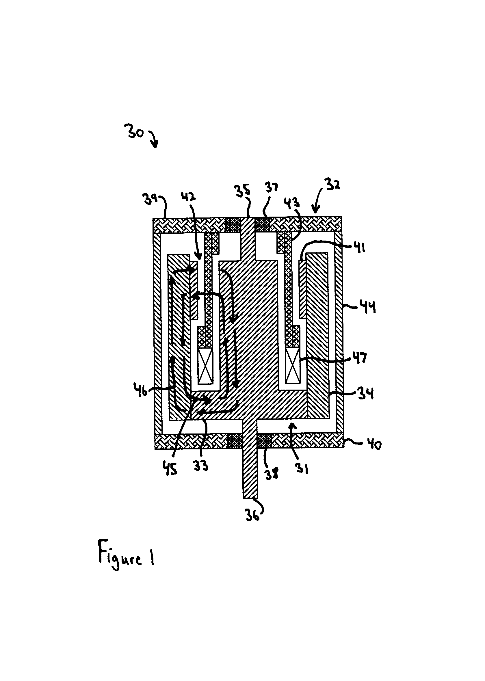
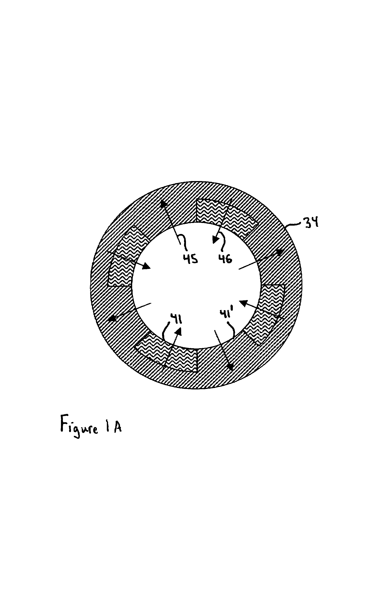
[0033]Turning to the drawings, wherein like reference characters designate identical or corresponding parts, a heteropolar hybrid alternator motor 30 shown in FIG. 1 includes a rotor 31 mounted for rotation within a stationary stator 32. The rotor 31 has a cylindrical ring portion 34 attached to a central core portion 33, both made of ferromagnetic material such as steel. A plurality of alternating, spaced apart permanent magnet poles 41 and ferromagnetic poles 41′ are arranged in a regularly spaced array around the inner circumference of the ring portion 34, as shown in FIG. 1A. The poles 41 and 41′ face an armature air gap 42 that is created between the two portions 33, 34 of the ferromagnetic rotor 31. In this configuration of the invention the permanent magnet poles 41 are located on an inner circumference of the outer ring 34 so that the ferromagnetic rotor structure radially reinforces the magnets 41 against centrifugal loading. The permanent magnets 41 generate permanent magn...


PUM


Abstract

A brushless hybrid electrical machine for converting between electrical and mechanical energy has a rotor supported for rotation about an axis of rotation relative to a juxtaposed stator that is stationary and magnetically interacts with the rotor. The rotor includes a ferromagnetic rotor structure having two portions spaced apart, but rotating together, and defining therebetween an armature air gap. Magnetic poles are arranged in a circumferentially alternating array of ferromagnetic and permanent magnet poles, bordering the air gap. A stationary air core armature having multiple phase windings is located in the armature air gap, and a field coil is also positioned between the two portions of the rotor for generating field coil flux that flows in a flux path through the ferromagnetic poles, the armature air gap and through the ferromagnetic rotor structure. The permanent magnet poles generate permanent magnet flux that also flows in a flux path through the armature air gap and through the ferromagnetic rotor structure. The field coil flux and the permanent magnet flux induces an AC voltage in the multiple phase windings of the air core armature as said rotor rotates.

Description

[0001]This is related to U.S. Provisional Application No. 60 / 394,374 filed on Jul. 8, 2002 and entitled “Compact Heteropolar Hybrid Alternator-Motor”.[0002]This invention pertains to electrical machines for converting between electrical and mechanical energy and more particularly to a heteropolar hybrid alternator / motor that has an array of ferromagnetic and permanent magnet poles around a circumference, wherein the ferromagnetic poles are magnetized by a stationary field coil. Fluxes from both the ferromagnetic poles and permanent magnet poles pass through an air core armature located in a magnetic air gap in the rotor. The fluxes travel in the same or opposite directions through the rotor depending on the polarity of the field coil current and allow control of the back emf generated in the armature. The heteropolar hybrid electrical machine has increased efficiency and more compact, lower cost construction than previous devices.BACKGROUND OF THE INVENTION[0003]Electrical motors an...

Claims


Application Information

Patent Timeline
IPC IPC(8): H02K1/00H02K3/00
CPCH02K3/47H02K21/24H02K21/12
Inventor GABRYS, CHRISTOPHER W.
Owner REVOLUTION ELECTRIC MOTOR
Why Eureka
Try Eureka