
High frequency scanning SQUID microscope and method of measuring high frequency magnetic fields

a high-frequency scanning and microscope technology, applied in the field of magnetoscopy, can solve the problem that the bandwidth of squid microscopes has not exceeded a few mhz, and achieve the effect of extending the bandwidth of scanning squid microscopes and extending the bandwidth of squid measurements

Inactive Publication Date: 2006-09-12
NATIONAL SECURITY AGENCY +1
View PDF2 Cites 15 Cited by
  • Summary
  • Abstract
  • Description
  • Claims
  • Application Information

AI Technical Summary

Benefits of technology

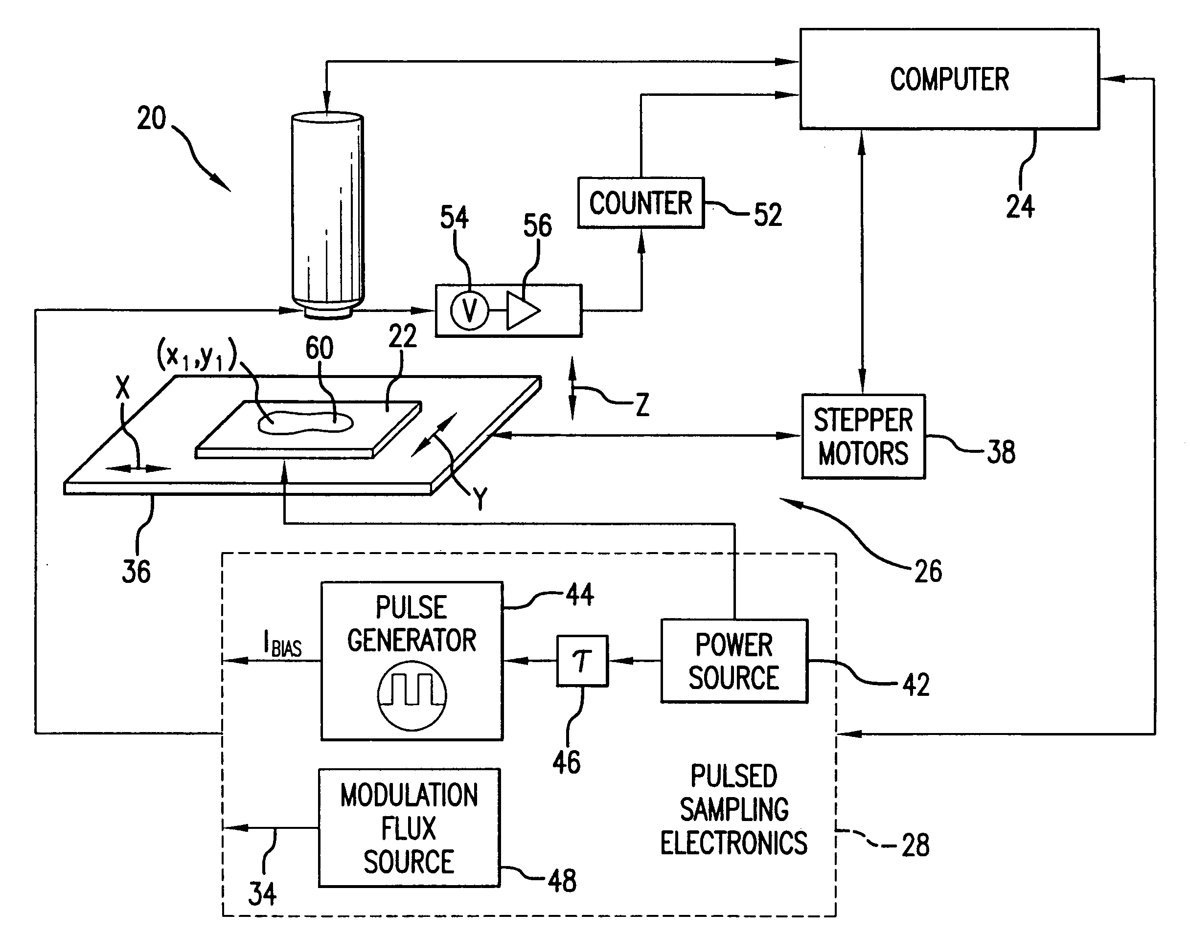
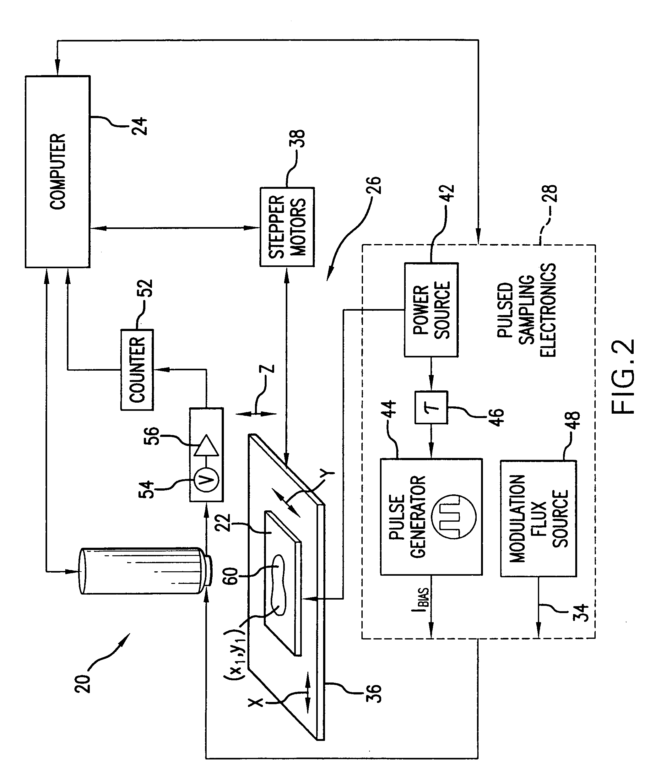
"The present invention provides a high frequency scanning SQUID microscope capable of measuring magnetic fields in the range of GHz. The microscope uses a hysteretic SQUID sensor and a pulsed sampling technique to measure magnetic fields emanating from a sample under study. The hysteretic SQUID is pulse biased and pulsed sampling is initiated at a predetermined time point by an additional DC modulating flux. The value of the modulation flux is set to cause at least one switching event in the hysteretic SQUID. The SQUID microscope also includes a scanning unit to change the relative position between the hysteretic SQUID sensor and the object under study, a power source to activate the hysteretic SQUID sensor, and a pulsed sampling unit to apply a pulsed bias current and magnetic modulation flux to the hysteretic SQUID. The SQUID microscope can measure magnetic fields with high accuracy and at high frequencies."

Problems solved by technology

Disadvantageously, with the present technology, the bandwidth of SQUID microscopes has not exceeded a few MHz.

Method used


Image

  • High frequency scanning SQUID microscope and method of measuring high frequency magnetic fields
  • High frequency scanning SQUID microscope and method of measuring high frequency magnetic fields
  • High frequency scanning SQUID microscope and method of measuring high frequency magnetic fields

Examples


Embodiment Construction

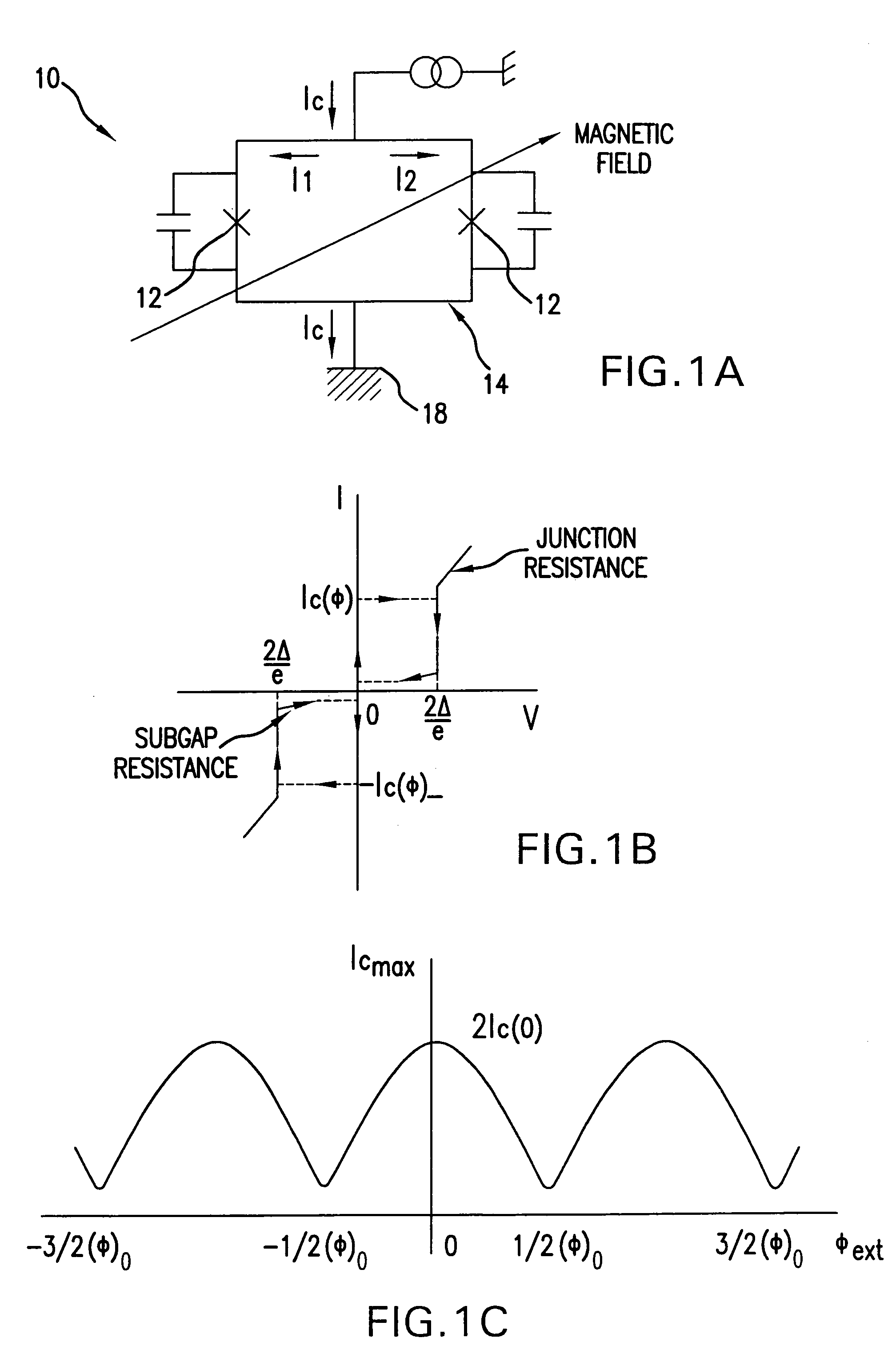
[0057]Referring to FIG. 1A, a hysteretic SQUID 10 is shown including a pair of capacitively shunted Josephson junctions 12. The SQUID device, being used as a magnetometer, is based on the interaction between the magnetic flux and the Josephson junction(s). The magnetic flux modulates the current passing through the junction, which is detected and amplified by feedback electronics. The main part of the SQUID 10 is the dual junction superconducting loop (SQUID loop) 14 carrying a critical supercurrent Ic. In FIG. 1A, the currents I1 and I2 are the junction currents with each passing through a respective junction 12. The critical supercurrent flows in the SQUID loop 14 as long as a source 16 and a sink (or ground) 18 are connected thereto. The critical super-current Ic is a maximum current that loop 14 will carry without developing a potential difference. The interference effect used in the SQUID 10 is the modulation of the super-current by an applied magnetic field passing through the...


PUM


Abstract

A scanning SQUID microscope capable of high frequency magnetic field measurements uses a hysteretic SQUID detector and a pulsed sampling technique which permits to extend the bandwidth of the SQUID microscope to above GHz region. The system can be readily incorporated into a 4.2k scanning SQUID microscope for imaging chips at room temperature. By biasing the hysteretic SQUID with pulses of a predetermined amplitude, and adjusting a modulation flux applied to the hysteretic SQUID at a plurality of time delays between the activation of the sample under study and the bias pulse, the hysteretic SQUID can be switched on, and the modulation flux value corresponding to such a switching event as a function of time is considered as representation of the magnetic field emanating from the sample under study.

Description

REFERENCE TO RELATED APPLICATIONS[0001]This Utility Patent Application is based on Provisional Patent Application Ser. No. 60 / 553,915, filed 17 Mar. 2004.FIELD OF THE INVENTION[0002]The present invention relates to magnetic microscopy; and in particular, for magnetically obtaining images of electrical currents flowing in microelectronic structures by means of scanning SQUID microscopes.[0003]More in particular, the present invention relates to high frequency scanning SQUID microscopes with a bandwidth extended into the GHz range. The high frequency scanning of magnetic fields is conducted with pulsed sampling of the magnetic field with a hysteretic SQUID.[0004]The present invention further relates to high frequency measurements of magnetic fields emanating from an object under study, particularly, for obtaining the images of electrical currents flowing in microelectronic structures for non-destructive evaluation of the structures and location of possible defects. Specifically, the m...

Claims


Application Information

Patent Timeline
Patent Type & Authority Patents(United States)
IPC IPC(8): G01R33/02G01R33/035G01R33/038
CPCB82Y35/00G01R33/0354G01R33/0385G01Q60/54B82Y25/00Y10S505/846
Inventor MATTHEWS, JOHNWELLSTOOD, FREDERICK CHARLESKWON, SOUN PILVLAHACOS, KOSTA P.
Owner NATIONAL SECURITY AGENCY
Learn More