Liquid crystal display device

a liquid crystal display and display device technology, applied in the field of liquid crystal display, can solve the problems of switching noise at the time of dimming, difficult to obtain proper lighting of fluorescent lamps, and simple circuit configuration of voltage dimming technology

Inactive Publication Date: 2006-09-12
PANASONIC CORP
View PDF11 Cites 42 Cited by
  • Summary
  • Abstract
  • Description
  • Claims
  • Application Information

AI Technical Summary

Benefits of technology

[0013]A liquid crystal display device of the present invention displays images by irradiating a liquid crystal panel (11), which is driven in response to video signals, with light outputted from a backlight device (15). The liquid crystal display device comprises: drive means (10 and 14) for driving the liquid crystal panel in response to the video signals in a manner such that one frame period is divided into a black display period and an image display period; a PWM dimming signal generation circuit (17) for generating a PWM dimming signal for controlling the backlight device by a PWM dimming technique; a lighting circuit (16) for driving the backlight device in response to the PWM dimming signal; and means (18, 28, 34, and 53) for controlling a cycle and / or phase of the PWM dimming signal to prevent occurrence of interference fringes in the liquid crystal panel, caused by the PWM dimming technique.

Problems solved by technology

The voltage dimming technique, though its circuit configuration is simple, has drawbacks.
For example, when the drive voltage is low, proper lighting of the fluorescent lamp is difficult to obtain.
On the other hand, in the PWM dimming technique, though the luminance of the fluorescent lamp can be easily controlled, there is a drawback in that switching noise occurs at the time of dimming.

Method used


Image

  • Liquid crystal display device
  • Liquid crystal display device
  • Liquid crystal display device

Examples


embodiment 1

[0037](Embodiment 1)

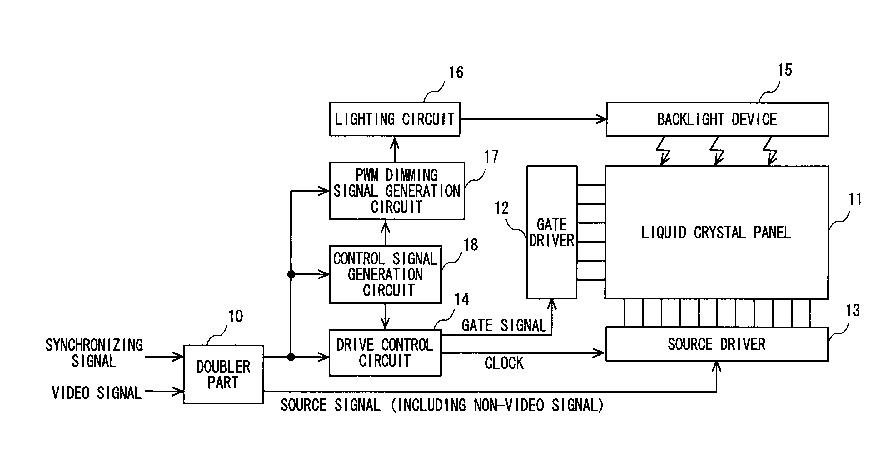
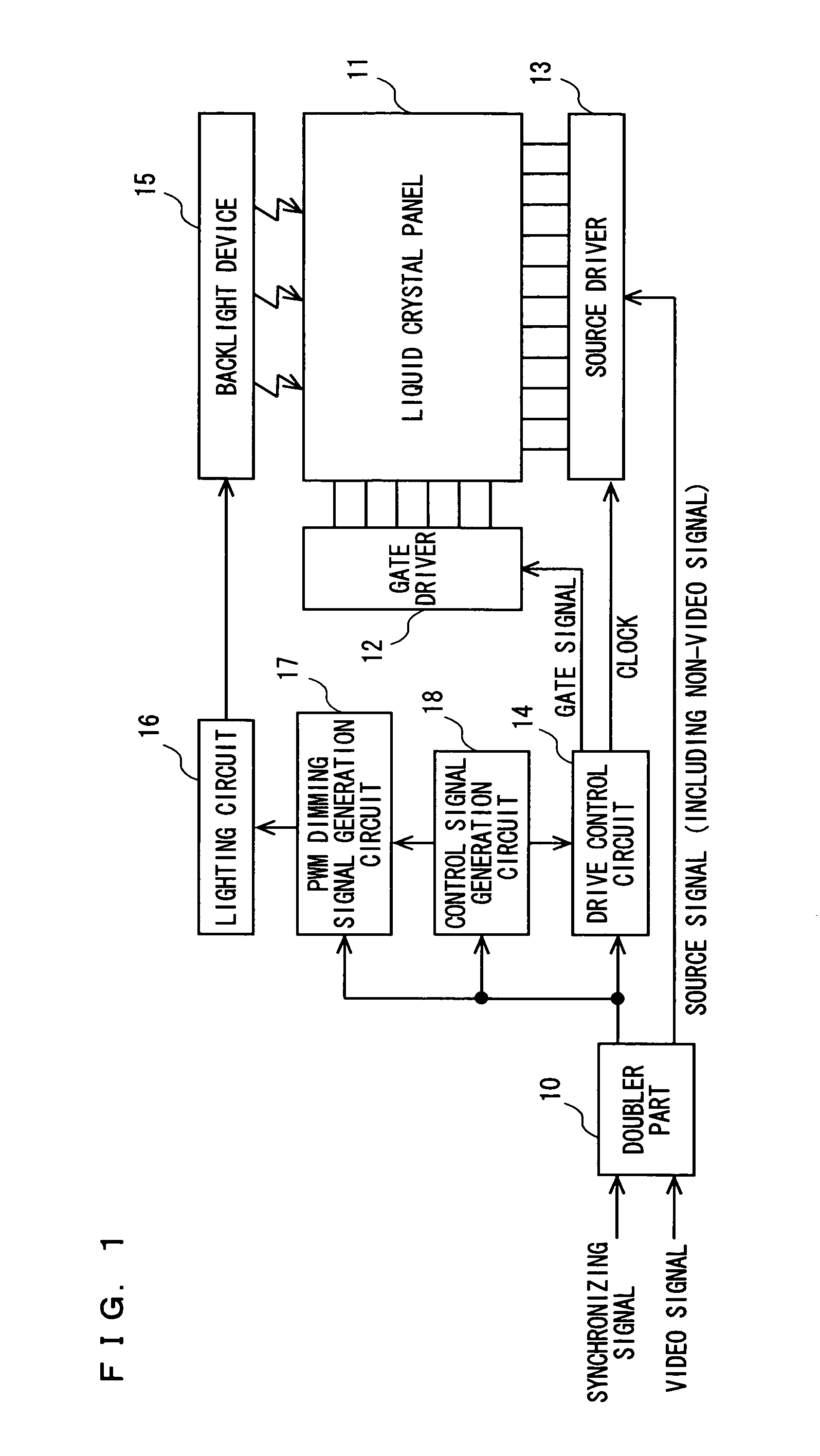
[0038]FIG. 1 is a block diagram showing the configuration of a liquid crystal display device according to Embodiment 1 of the present invention. The liquid crystal display device includes a doubler part 10, a liquid crystal panel 11, a gate driver 12, a source driver 13, a drive control circuit 14, a backlight device 15, a lighting circuit 16, a PWM dimming signal generation circuit 17, and a control signal generation circuit 18.

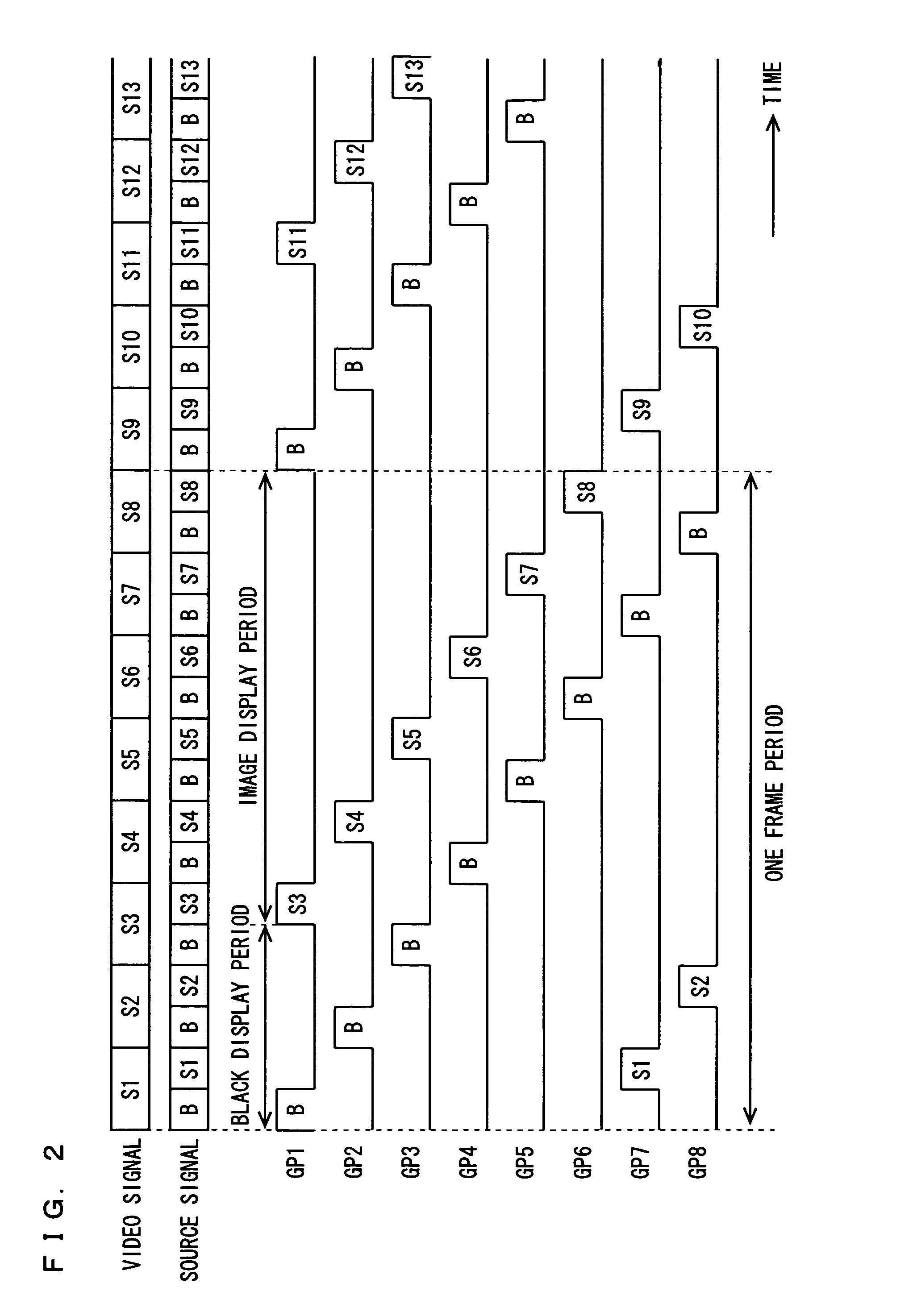
[0039]To the liquid crystal display device are fed video signals and a synchronizing signal. The doubler part 10 doubles the frequencies of the video signals in response to the video and synchronizing signals. Then, the doubler part 10 provides a source signal to the source driver 13 and also provides the frequency-doubled synchronizing signal to the drive control circuit 14, the control signal generation circuit 18, and the PWM dimming signal generation circuit 17. Here, as the source signal, as shown in FIG. 2, original video signals (S...

embodiment 2

[0047](Embodiment 2)

[0048]FIG. 4 is a block diagram showing the configuration of a liquid crystal display device according to Embodiment 2 of the present invention. The liquid crystal display device includes a doubler part 10, a liquid crystal panel 11, a gate driver 12, a source driver 13, a drive control circuit 14, a backlight device 15, a lighting circuit 16, a PWM dimming signal generation circuit 17, and a control signal generation circuit 28. In FIG. 4, the elements corresponding to those found in FIG. 1 are designated by like reference numerals and the descriptions thereof are omitted.

[0049]The control signal generation circuit 28 receives a synchronizing signal outputted from the doubler part 10, generates PWM dimming frequency information such that the PWM dimming frequency is (an odd number / 2) times the vertical frequency, and then provides such information to the PWM dimming signal generation circuit 17.

[0050]With reference to FIG. 5, the operation of the present embodim...

embodiment 3

[0055](Embodiment 3)

[0056]FIG. 6 is a block diagram showing the configuration of a liquid crystal display device according to Embodiment 3 of the present invention. The liquid crystal display device includes a doubler part 10, a liquid crystal panel 11, a gate driver 12, a source driver 13, a drive control circuit 34, a backlight device 15, a lighting circuit 16, and a PWM dimming signal generation circuit 17. In FIG. 6, the elements corresponding to those found in FIG. 1 are designated by like reference numerals and the descriptions thereof are omitted.

[0057]The drive control circuit 34 generates, in response to a synchronizing signal outputted from the doubler part 10, PWM dimming frequency information such that a PWM dimming frequency f and a black display ratio B satisfy the relationships f ≧25B+250 and B>10, and provides such information PWM dimming signal generation circuit 17.

[0058]With reference to FIG. 7, the principle of the present embodiment is described below.

[0059]The ...


PUM


Abstract

A doubler part doubles frequencies of video signals. A drive control circuit generates, in response to a synchronizing signal outputted from the doubler part, PWM dimming frequency information such that a PWM dimming frequency f and a black display ratio B satisfy the relationships f≧25B+250 and B>10, and provides such information to a PWM dimming signal generation circuit. In addition, the drive control circuit drives a gate driver and a source driver such that one frame period is divided into an image display period and a black display period. The PWM dimming signal generation circuit generates, in response to a synchronizing signal and the PWM dimming frequency information, a PWM dimming signal and provides the PWM dimming signal to a lighting circuit. The lighting circuit activates a backlight device with dimming, in response to the PWM dimming signal. This configuration reduces colored interference fringes in a liquid crystal display device resulting from the combination of a black insertion drive technique and a PWM dimming technique.

Description

TECHNICAL FIELD[0001]The present invention relates to a liquid crystal display, and more particularly to a liquid crystal display device that displays images by irradiating a liquid crystal panel, which is driven in response to video signals, with light outputted from a backlight.BACKGROUND ART[0002]Liquid crystal display devices are so-called hold-type image display devices in which the signal level is held, as shown in FIG. 17, for one frame period in each liquid crystal cell. For the types of liquid crystals used in liquid crystal display devices, conventionally, a TN (Twisted Nematic) mode liquid crystal is commonly used, but in recent years, in order to overcome the drawbacks of the TN-mode liquid crystal (e.g., a narrow viewing angle and a slow response time), liquid crystal display devices using an OCB (Optically Self-Compensated Birefringence) mode liquid crystal have been studied. Such devices are disclosed, for example, in Japanese Laid-Open Patent Publication Nos. 7-84254...

Claims


Application Information

Patent Timeline
Patent Type & Authority Patents(United States)
IPC IPC(8): G09G3/36G09G3/20G09G3/34
CPCG09G3/3406G09G3/3648G09G3/2018G09G2320/064G09G2320/0247G09G2320/0606G09G2320/0626G09G2310/061G02F1/133G09G3/36
Inventor KUMAMOTO, YASUHIROFUNAMOTO, TAROARIMOTO, KATSUYUKI
Owner PANASONIC CORP
Why Eureka
Try Eureka