Wavelength division multiplexed memory module, memory system and method

a memory module and wavelength division technology, applied in the field of computer systems, can solve the problems of reducing the effective memory bandwidth of computer systems and other devices using memory modules, and signal induced noise for a considerable period

Inactive Publication Date: 2006-09-12
MICRON TECH INC
View PDF259 Cites 29 Cited by
  • Summary
  • Abstract
  • Description
  • Claims
  • Application Information

AI Technical Summary

Problems solved by technology

Therefore, signal induced noise is present on the data bus for a considerable period after data have been written to the memory modules 10.
The need to provide for a settling time can markedly reduce the effective memory bandwidth of computer systems and other devices using memory modules.

Method used


Image

  • Wavelength division multiplexed memory module, memory system and method
  • Wavelength division multiplexed memory module, memory system and method
  • Wavelength division multiplexed memory module, memory system and method

Examples


Embodiment Construction

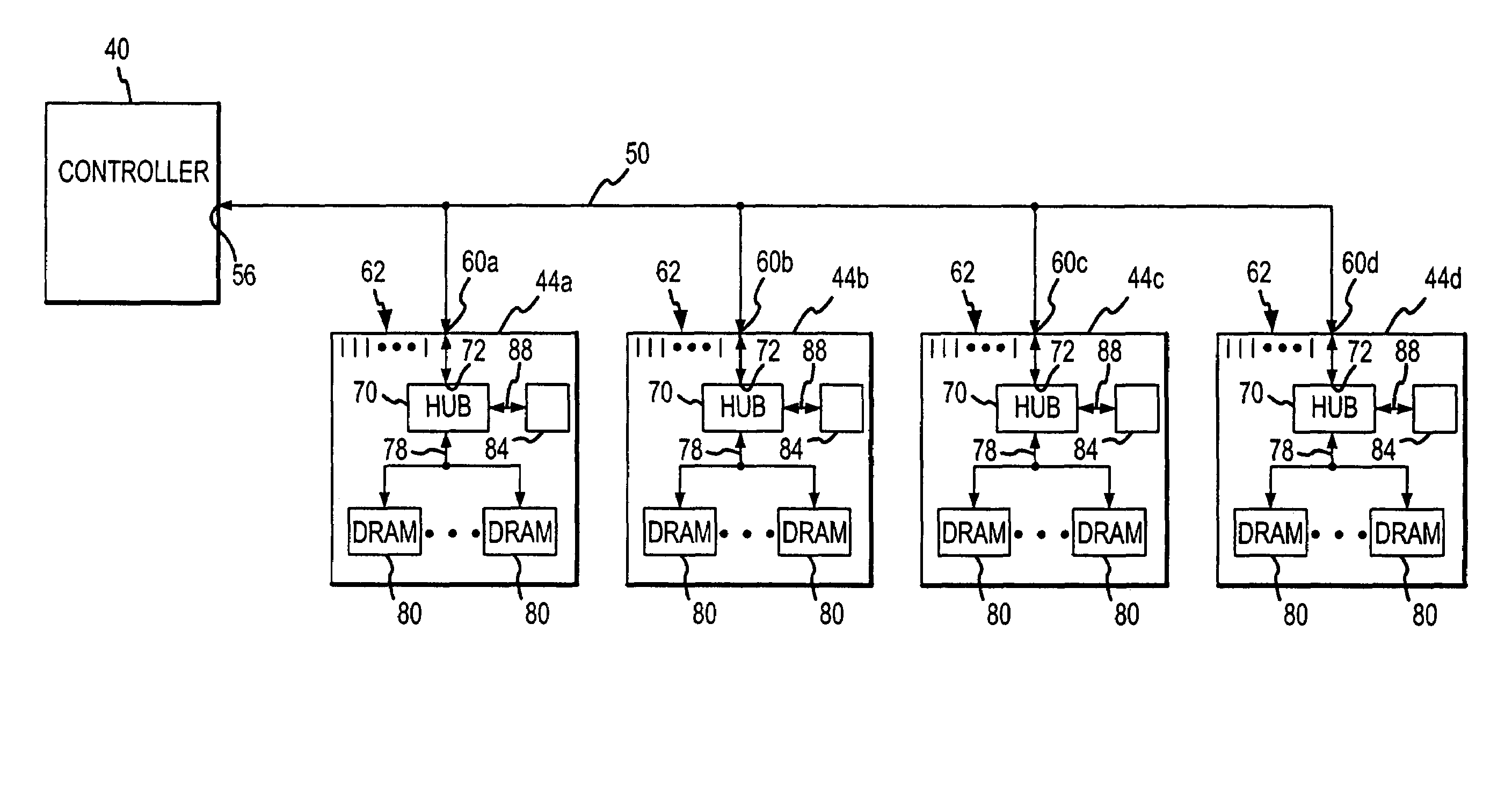
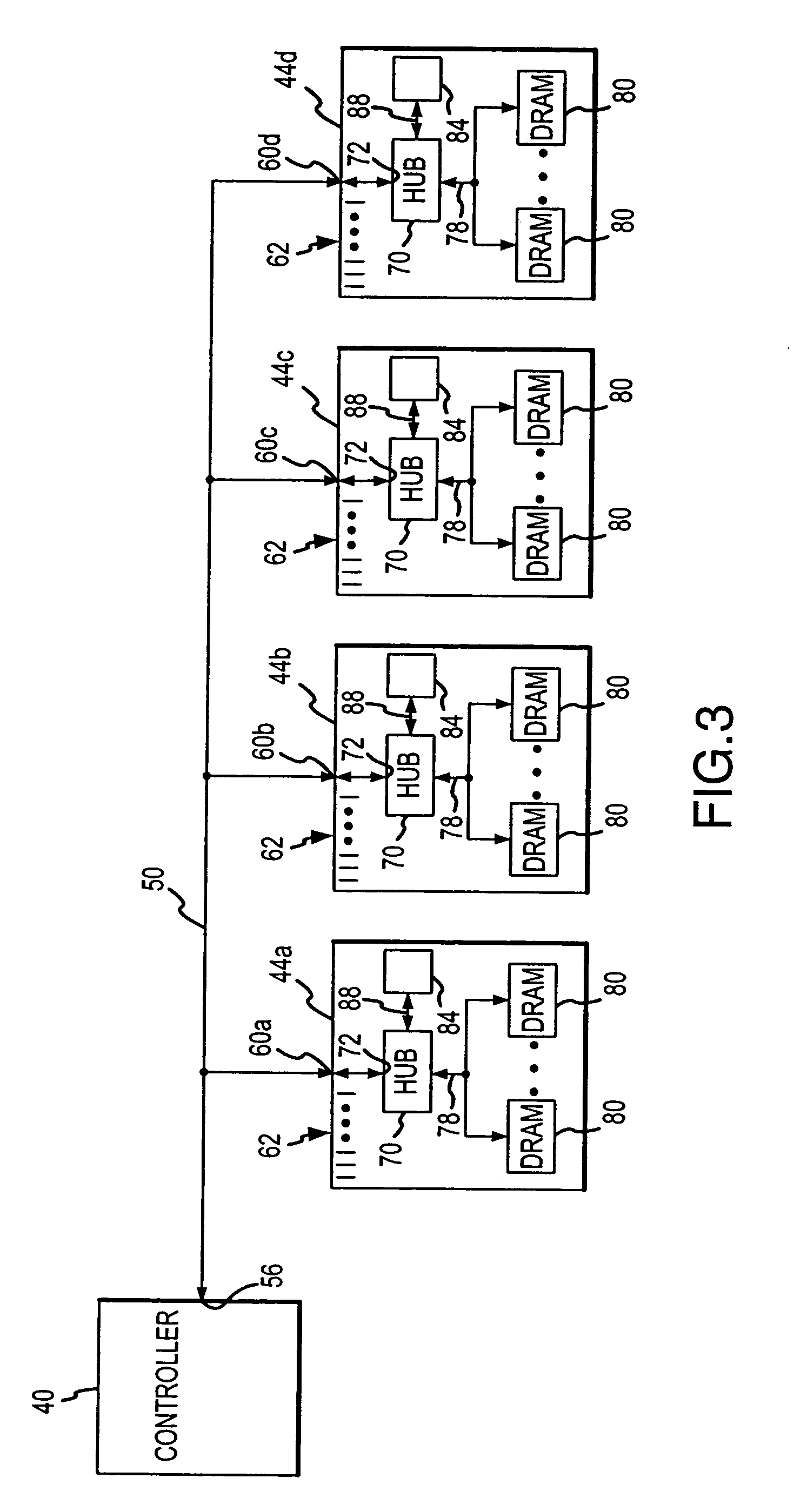
[0016]FIG. 3 is a block diagram of a portion of a computer system according to one example of the present invention. A controller 40, such as a system controller or a memory controller, is coupled to 4 memory modules 44a–d though an optical communication path 50, although a greater or less number of modules 44 may be coupled to the controller 40. The controller 40 and the memory modules 44a–d are coupled to the optical communication path 50 through optical input / output ports 56, 62a–d, respectively. The controller 40 may communicate with the memory modules 44 in any of a variety of communications protocols, but they preferably communicate using optical signal packets that contain data, address and command information. The optical communication path 50 may be one or more optical waveguides, such as optical fibers or waveguides mounted on printed circuit boards, free space, or some other optical coupling medium that allows light to be transmitted between the controller 40 and the memo...


PUM


Abstract

A computer system includes a controller linked to a plurality of memory modules each of which has an optical memory hub and several memory devices coupled to the memory hub. The controller communicates with the memory hubs by coupling optical signals to and from the memory hubs using an optical communication path, such as one or more optical waveguides. In one example of the invention, the memory modules transmit and receive optical signals having different wavelengths. In another example of the invention, the memory modules receive optical signals corresponding to memory command and address signals at different wavelengths, but they transmit and receive optical signals corresponding to memory commands at the same wavelength.

Description

CROSS-REFERENCE TO RELATED APPLICATION[0001]This application is a continuation of pending U.S. patent application Ser. No. 10 / 238,322, filed Sep. 9, 2002.TECHNICAL FIELD[0002]This invention relates to computer systems, and, more particularly, to a computer system having a memory hub coupling several memory devices to a processor or other memory access device.BACKGROUND OF THE INVENTION[0003]Memory modules are in common use in computer systems in the form of double in-line memory modules (“DIMMs”). An example of a conventional DIMM-type memory module 10 is shown in FIG. 1. The memory module 10 includes a circuit board substrate 14 on which several memory devices 20, typically dynamic random access memories (“DRAMs”), are mounted. In the DIMM-type memory module 10 shown in FIG. 1, 8 memory devices 20 are mounted on each side of the substrate 14. Terminals 24 are formed along an edge of the substrate 14, which mate with slotted connectors (not shown ) typically mounted on a computer sy...

Claims


Application Information

Patent Timeline
Patent Type & Authority Patents(United States)
IPC IPC(8): G11C5/06
CPCG11C5/063
Inventor LEE, TERRY R.JEDDELOH, JOSEPH M.
Owner MICRON TECH INC
Why Eureka
Try Eureka