System for controlling fluid flow

a fluid flow and fluid technology, applied in the field of fluid distribution, can solve the problems of affecting the uniformity of film thickness on the wafer, prior art semiconductor manufacturing systems suffer a further deficiency, and leave droplets in the nozzle, and achieve the effect of reducing the crystallization of fluid droplets

Active Publication Date: 2006-09-12
ENTEGRIS INC
View PDF7 Cites 16 Cited by
  • Summary
  • Abstract
  • Description
  • Claims
  • Application Information

AI Technical Summary

Benefits of technology

[0007]Embodiments of the present invention provide a system and method of controlling fluid flow that eliminates, or at least substantially reduces, the shortcomings of prior art fluid flow control systems and methods.
[0014]Embodiments of the present invention provide an advantage over prior art systems and methods of ending dispense processes by closing a fluid control valve in such a manner that the likelihood that excess fluid drops will hit a wafer after the end of the dispense process is reduced.
[0015]Embodiments of the present invention provide yet another advantage by reducing the crystallization of fluid droplets in a dispense nozzle after the dispense process has ended.
[0016]Embodiments of the present invention provide another advantage by enabling a user to employ any number of techniques using the same set of computer instructions to resolve close control issues for any number of applications, including different flow rates, dispense system setups and dispense fluids.

Problems solved by technology

This can cause the fluid to severely oscillate at the end of the dispense process, potentially causing droplets or excess fluid to drip onto the wafer, thereby affecting the uniformity of film thickness on the wafer.
Whether an open / close valve or proportional valve with predetermined rate of closure is employed, prior art semiconductor manufacturing systems suffer a further deficiency.
Drawing the fluid back into the nozzle too quickly can leave droplets in the nozzle.
These droplets can crystallize, leading to problems in the next dispense process.

Method used


Image

  • System for controlling fluid flow
  • System for controlling fluid flow
  • System for controlling fluid flow

Examples


Embodiment Construction

[0029]Preferred embodiments of the invention are illustrated in the FIGURES, like numerals being used to refer to like and corresponding parts of the various drawings.

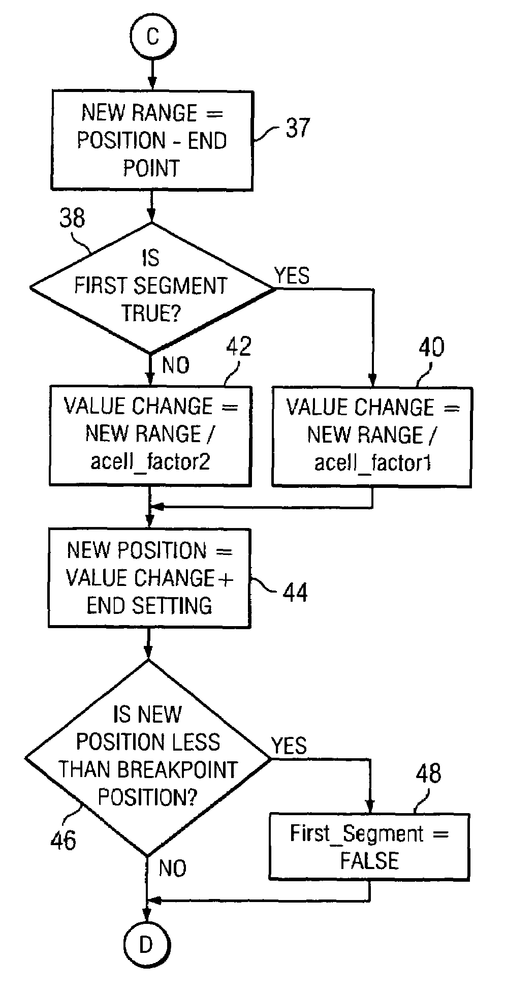
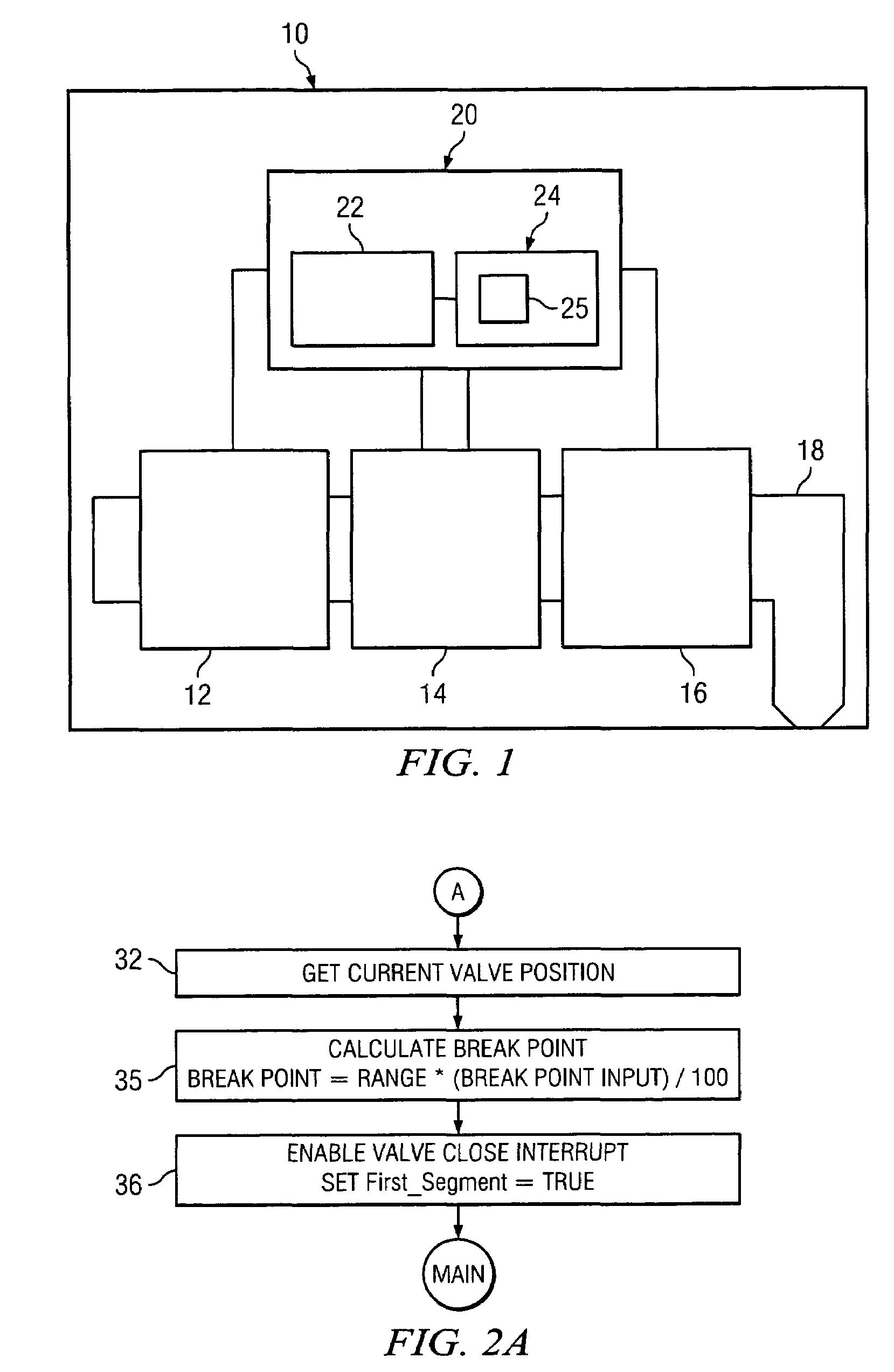
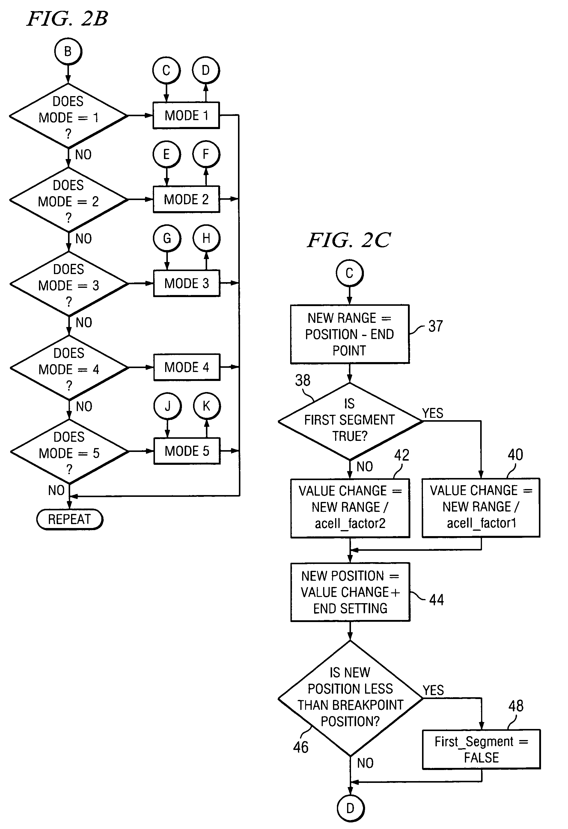
[0030]Embodiments of the present invention provide systems and methods of controlling fluid dispense to ensure clean break off of fluid at the end of a dispense process and to reduce crystallization of fluid in the dispense nozzle. One embodiment of the present invention can include a controller that can generate a flow control signal according to a first close rate parameter to cause a control valve to close for a first segment of the close range and to generate the flow control signal according to a second close rate parameter to cause the control valve to close for a second segment of the close range. The close rate parameter can result in closing the valve at a controlled rate, change in rate, or change in rate of change. By adjusting the close rate parameters, severe oscillation at the end of the dispense process ...


PUM


Abstract

Embodiments of the present invention provide systems and methods of controlling fluid dispense to ensure clean break off of fluid at the end of a dispense process and to reduce crystallization of fluid in the dispense nozzle. One embodiment of the present invention can include a controller that can, generate a flow control signal to cause a control valve to close according to a first close rate parameter for a first segment of the close range and to generate the flow control signal to cause the control valve to close according to a second close rate parameter for a second segment of the close range.

Description

TECHNICAL FIELD OF THE INVENTION[0001]The present invention relates generally to the field of dispensing fluids. More particularly, the present invention relates to systems and methods of controlling fluid flow at the end of a dispense process.BACKGROUND OF THE INVENTION[0002]The manufacture of semiconductors often requires dispensing various liquids on a silicon wafer. In Spin-On Glass (“SOG”) methods, a SOG material, typically a silicon dioxide solution, is dispensed by a nozzle onto the center of a silicon wafer. The wafer is then immediately rotated at a high speed, spreading the SOG material across the wafer. The amount of SOG material dispensed, surface tension of the SOG material solution, viscosity of the SOG material solution, the oxide concentration of the SOG material and the spin rate of the wafer affect the resulting film thickness.[0003]In many semiconductor manufacturing systems, pumps and valves are used to control the amount of liquid dispensed from the nozzle. Duri...

Claims


Application Information

Patent Timeline
Patent Type & Authority Patents(United States)
IPC IPC(8): G05D7/00G05D13/00G05D7/06G05D11/00
CPCG05D7/0635H01L21/6715Y10T137/0989G05D7/00G05D11/00
Inventor LAVERDIERE, MARCMCLOUGHLIN, ROBERT F.
Owner ENTEGRIS INC
Why Eureka
Try Eureka