Foam molding method and apparatus

a molding method and foam technology, applied in the field of foam molding, can solve problems such as video disturbance phenomena, dropout phenomena, etc., and achieve the effects of increasing the concentration of the mixture in the mold, increasing the injection amount, and raising the holding pressur

Inactive Publication Date: 2006-09-12
CANON KK
View PDF30 Cites 12 Cited by
  • Summary
  • Abstract
  • Description
  • Claims
  • Application Information

AI Technical Summary

Benefits of technology

[0034]During the playback of information recorded on the recording medium in the audio equipment or video equipment, the playback of information may be disturbed by vibrations or shocks outside the equipment. It is an object of the present invention to provide a resin molded product which solves this problem.
[0078]The charged resin is cooled from its surface owing to the transfer of heat to the mold and escaping of heat. As the cooling gradient increases, the resin is cooled faster. This shortens the foaming time. As a result, the diameters of cells decrease.

Problems solved by technology

When the recording medium set in the audio equipment or video equipment is driven by a driving means such as a motor to play back audio information or video information, a dropout phenomenon or video disturbance phenomenon is caused by the vibrations generated by the driving means or external shocks.

Method used


Image

  • Foam molding method and apparatus
  • Foam molding method and apparatus
  • Foam molding method and apparatus

Examples


first embodiment

(First Embodiment)

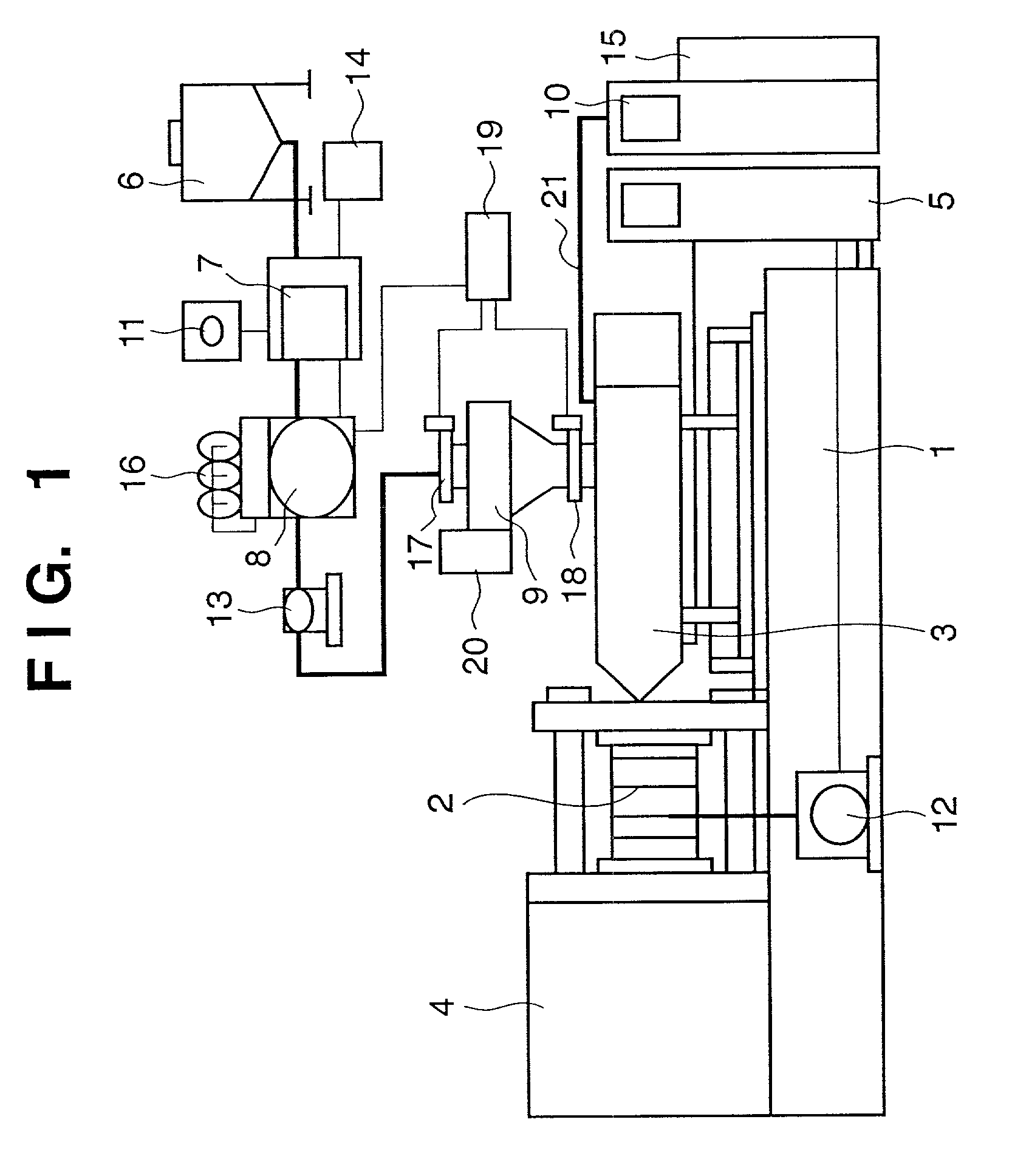
[0115]The first characteristic feature of this embodiment is that resin chips or pellets are processed by a dehumidifier / dryer connected to a vacuum pump and inert gas feeder. In general, it takes as much time as 24 hr or more to let an inert gas permeate in pellets at a temperature equal to or lower than the melting temperature of a resin. Because of poor productivity and difficulty in commercialization, a method of directly blowing a gas into a molten resin in a plasticizing unit and mechanically mixing the resin and gas is used. The present inventor found that the permeating rate of a gas could be greatly increased by making pellets come into contact with a gas after the pellets were evacuated and dehumidified. This leads to the pre-processing step in this embodiment. As in this embodiment, when an inert gas is made to permeate pre-processed chips or pellets at a temperature equal to or lower than the melting temperature of the resin in an inert gas permeation u...

second embodiment

(Second Embodiment)

[0149]The second embodiment of the present invention will be described below with reference to FIGS. 13 to 17.

[0150]FIG. 13 shows the outer appearance of audio or video equipment 102 for playing back musical information or video information recorded on a disk 101.

[0151]FIG. 14 is a view for explaining the main part of the internal structure of the video equipment 102. The above compact disk 101 is rotated at a high speed by a rotating / driving means 104, and the information recorded on the surface of the disk 101 is read by a pickup means 106 and subjected to playback processing. The user can listen to the resultant music output from an information output portion through earphones or the like.

[0152]The driving means 104 includes a rotating / driving means such as a motor and rotates the disk 101 at a high speed through a bearing portion.

[0153]Reference numeral 108 denotes a housing case for the equipment; and 110, an upper cover member.

[0154]Reference numerals 112 an...

third embodiment

(Third Embodiment)

[0170]FIGS. 18, 19, and 20 are views for explaining the third embodiment of the present invention.

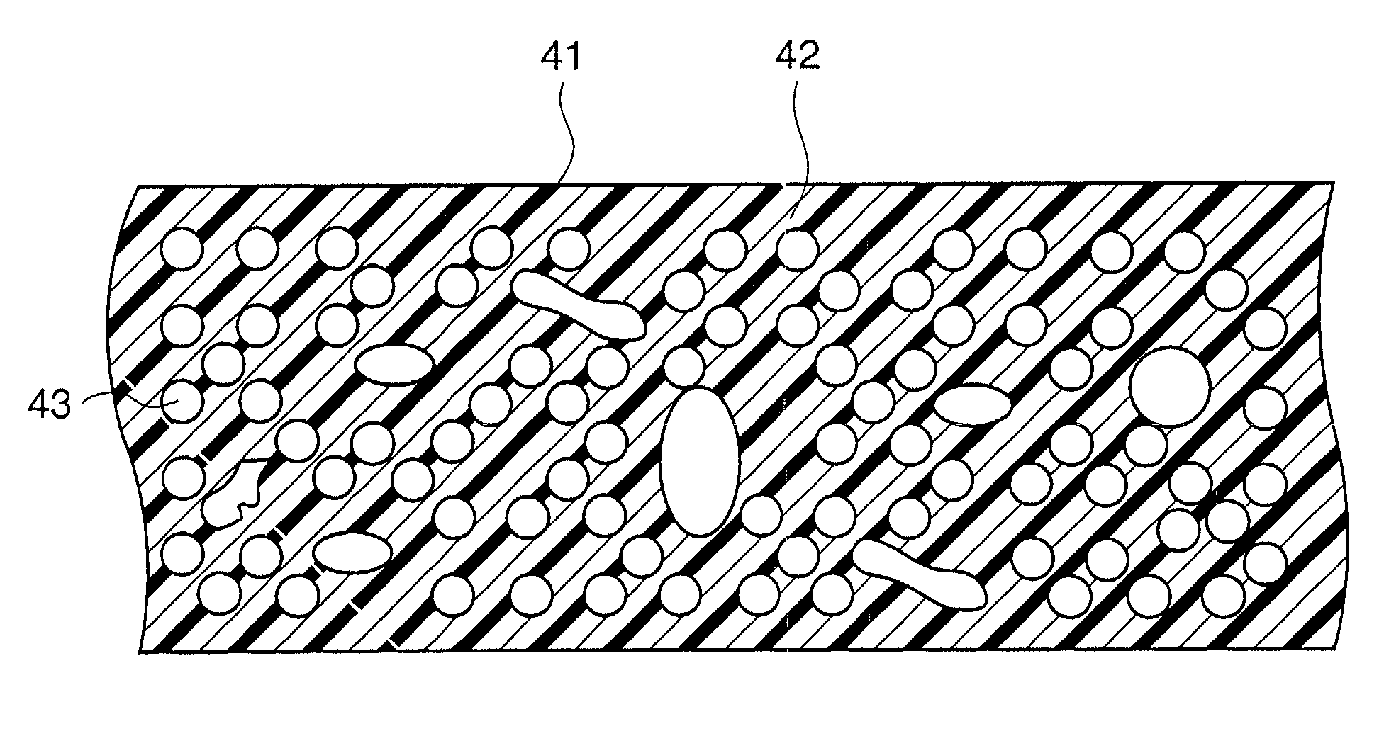
[0171]FIG. 18 is a schematic sectional view of a resin molded product according to this embodiment.

[0172]Cells 140A, 140B, and 140C existing in a resin molded product 140 of this embodiment vary in diameter depending on their positions in the resin molded product from its surface.

[0173]As shown in FIG. 18, each cell 140A located near a surface 140a of the molded product 140 has the smaller diameter than cells in other places, and each cell 140C at the central position in the molded product has the larger diameter than cells in other places. Each cell 140B located between the surface and the central portion has an intermediate diameter.

[0174]That is, the cells existing in the resin molded product 140 of this embodiment gradually decrease in diameter from the central portion in the direction of thickness to the surface portion of the molded product.

[0175]Shocks and vibra...


PUM

PropertyMeasurementUnit
sizeaaaaaaaaaa
sizesaaaaaaaaaa
pressureaaaaaaaaaa

Abstract

According to this invention, there is provided a molding method and apparatus which increase the gas permeation speed in obtaining a foamed resin molded product by letting a gas permeate a molten resin material. To achieve this object, a chip- or pellet-like resin material is evacuated and subjected to dehumidifying / drying processing, and replacement processing in an inert gas in a pre-processing unit, the resin material is then held in an inert gas of a predetermined temperature and pressure in an inert gas permeation unit for a predetermined period of time, the temperature and pressure are decreased, the material is fed to a material hopper whose temperature and pressure are controlled, the material is fed to a plasticizing unit to which a gas of a predetermined temperature and pressure is fed, the resin material is melted in the plasticizing unit, the resin material is injected / charged into a mold which is evacuated in advance to a pressure not more than atmospheric pressure, the pressure is restored to atmospheric pressure after the resin material is cooled for a predetermined period of time, and a foamed product is extracted by opening the mold.

Description

FIELD OF THE INVENTION[0001]The present invention relates to foam molding in which an inert gas such as carbon dioxide gas is used as a foaming agent and a resin is charged into a mold.[0002]The present invention also relates to a resin molded product molded from a resin material.[0003]The present invention further relates to a structural member manufactured from a resin material.[0004]The present invention further relates to a resin molded product used for an audio / musical instrument using a compact disk (to be referred to as a CD hereinafter) and a resin molded product used for video equipment using a digital video disk (to be referred to as a DVD hereinafter), video tape, or the like.[0005]The present invention further relates to an antivibration mechanism and antivibration member.[0006]The present invention further relates to a screw fastening member suitable for an antivibration mechanism.[0007]The present invention further relates to a method of processing an antivibration mem...

Claims


Application Information

Patent Timeline
Patent Type & Authority Patents(United States)
IPC IPC(8): G11B33/08G11B33/00B29C44/04B29C44/34
CPCB29C44/04B29C44/3461B29C44/3453
Inventor ARAI, TAKASHI
Owner CANON KK
Why Eureka
Try Eureka