Failure diagnosis apparatus for secondary air supplier

a secondary air supplier and failure diagnosis technology, applied in mechanical devices, electric control, machines/engines, etc., to achieve the effect of accurately determining failures

Active Publication Date: 2006-09-19
TOYOTA JIDOSHA KK
View PDF17 Cites 6 Cited by
  • Summary
  • Abstract
  • Description
  • Claims
  • Application Information

AI Technical Summary

Benefits of technology

[0007]An object of the present invention is to provide failure diagnosis a...

Problems solved by technology

The pressure pulsations detected by the pressure sensor in the secondary air supply system include one due to the exhaust puls...

Method used


Image

  • Failure diagnosis apparatus for secondary air supplier
  • Failure diagnosis apparatus for secondary air supplier
  • Failure diagnosis apparatus for secondary air supplier

Examples


Embodiment Construction

[0031]The preferred embodiments of the present invention will be described below in detail with reference to the accompanying drawings. For easier understanding of description, the same components will be denoted by the same reference symbols throughout the drawings as much as possible, without redundant description.

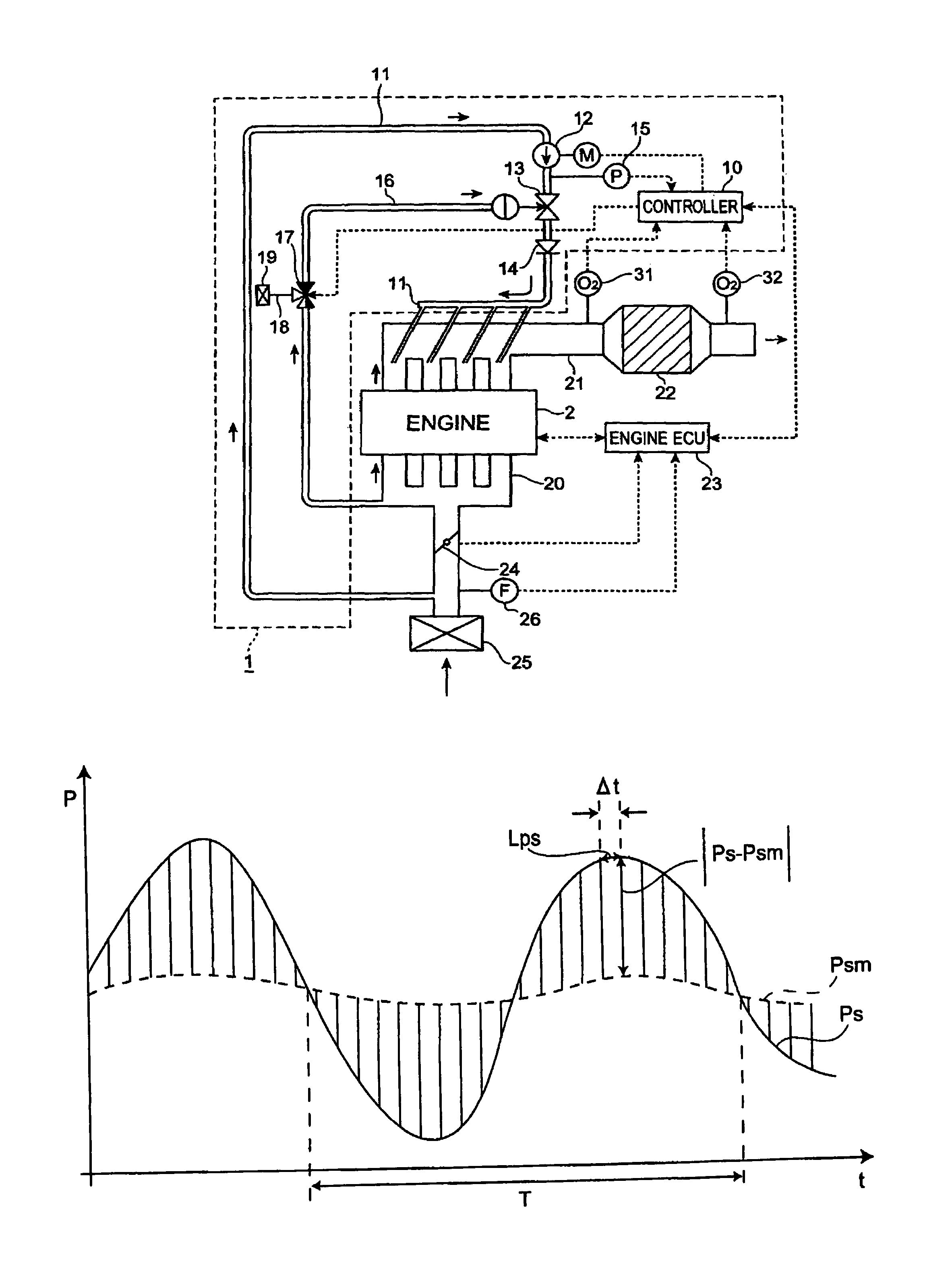
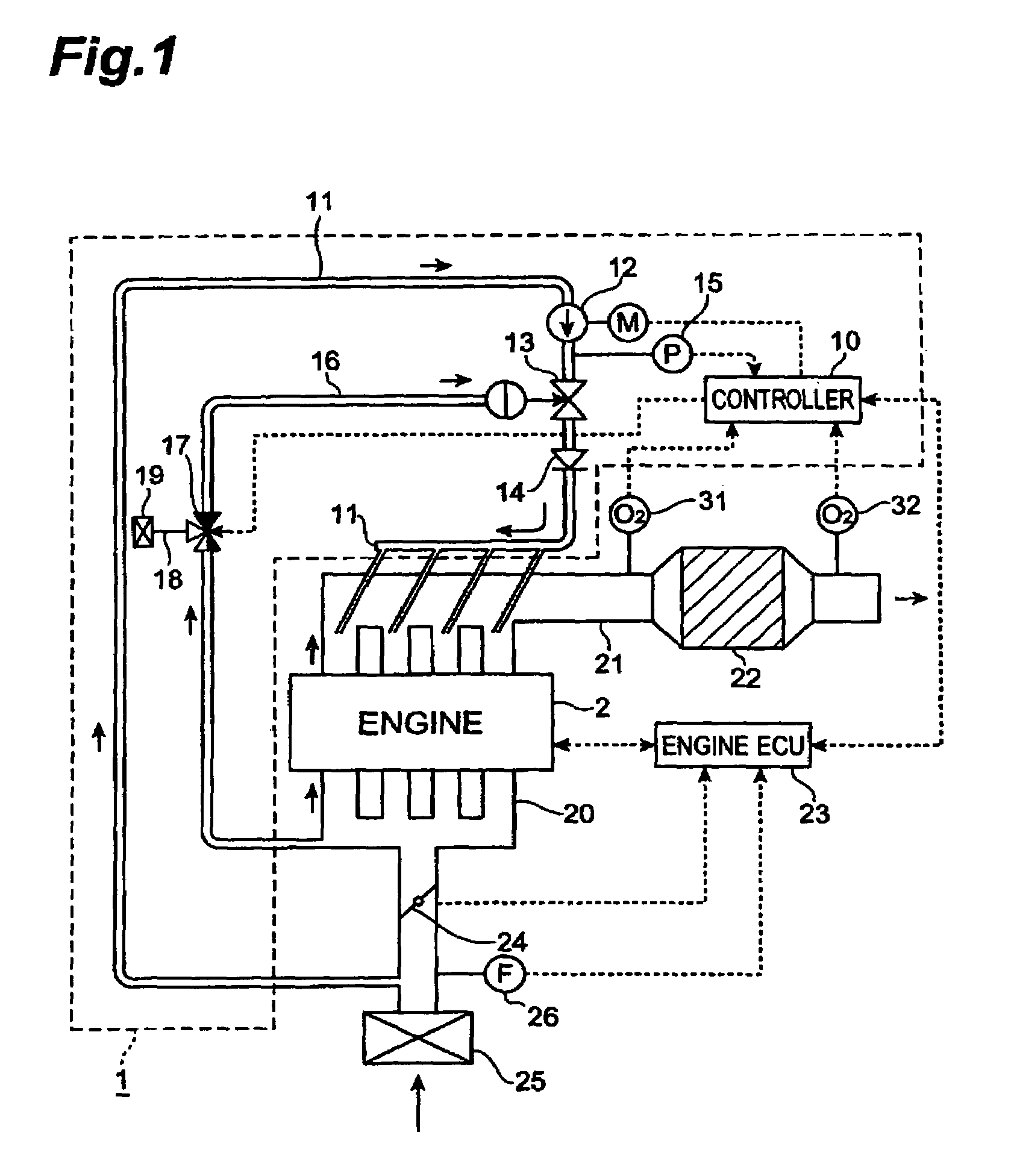
[0032]FIG. 1 is a schematic view showing the configuration of the internal combustion engine equipped with the secondary air supplier including the failure diagnosis apparatus of the present invention. This secondary air supplier 1 is attached to a multi-cylinder gasoline engine (hereinafter referred to simply as an engine) 2 being an internal combustion engine. An intake pipe (manifold) 20 and an exhaust pipe (manifold) 21 are attached to the engine 2, and a throttle 24 is placed on the intake pipe 20. An intake air filter 25 is attached to an end of the intake pipe 20. An air flow meter 26 for measuring a quantity of air (quantity of primary air) is placed between the ...


PUM


Abstract

A failure diagnosis apparatus for secondary air supplier according to the present invention determines a failure of a secondary air supplier based on pressure and pressure pulsation in a secondary air supply path. A failure diagnosis is made by determining the presence or absence of pressure pulsation in the secondary air supply path based on a determination threshold, and in the present invention the determination threshold is varied according to a pressure value in the secondary air supply path (a smoothed value or an average value of measured pressure). This permits the apparatus to make an accurate failure diagnosis, while eliminating pressure pulsations except for that due to exhaust pulsation (e.g., that due to noise of the pressure sensor and that caused by surging of an air pump).

Description

BACKGROUND OF THE INVENTION[0001]1. Field of the Invention[0002]The present invention relates to secondary air suppliers for supplying secondary air to upstream of an emission purifying device of an internal combustion engine and, more particularly, to a failure diagnosis apparatus of the secondary air supplier capable of detecting an anomaly of a component thereof[0003]2. Related Background Art[0004]An example of the known emission control systems of internal combustion engine is an apparatus with a three way catalyst in the exhaust system to reduce CO, HC, and NOx components in exhaust gas and thereby clean up exhaust emissions. Furthermore, there is a known technique of connecting a secondary air supply path equipped with a switching valve, to an exhaust manifold, and pressure-feeding air (secondary air) into the exhaust manifold by means of an air pump to increase the oxygen content in exhaust, thereby effecting the cleanup based on promotion of oxidation of HC and CO in exhaust...

Claims


Application Information

Patent Timeline
IPC IPC(8): F01N3/00F02D45/00F01N3/22F01N3/32F01N3/34F02D41/22
CPCF01N3/22F01N3/34F02D41/221F01N2550/14Y02T10/42Y02T10/40Y02T10/20Y02T10/12
Inventor HIROOKA, SHIGEMASA
Owner TOYOTA JIDOSHA KK
Why Eureka
Try Eureka