Carburetor hat for forced induction system

a technology of forced air induction and carburetor hat, which is applied in the direction of heating types, separation processes, applications, etc., can solve the problems of inability to deliver the proper mixture to the combustion chamber, the prior art carburetor hat is problematic and subject to several undesirable limitations, etc., to achieve the effect of facilitating the fluid inline movement and optimum pressure balan

Inactive Publication Date: 2006-09-19
ACCESSIBLE TECHONOLOGIES
View PDF17 Cites 14 Cited by
  • Summary
  • Abstract
  • Description
  • Claims
  • Application Information

AI Technical Summary

Benefits of technology

[0007]The present invention provides an improved carburetor hat that does not suffer from the problems and limitations of the prior art carburetor hats detailed above. The inventive carburetor hat divides the induction fluid flowing through the hat and prevents the fluid from thrusting against the back wall of the hat and stacking up in the hat. The improved hat is particularly well suited for use in combination with a forced air induction system utilizing a compressor. The inventive carburetor hat facilitates inline movement of the fluid and thus enables a more optimum pressure balance with the carburetor.

Problems solved by technology

As these pressure conditions become unbalanced, the carburetor will not draw the proper mixture of fuel and induction fluid and thus will not deliver the proper mixture to the combustion chamber(s).
Without the proper mixture, the engine will undesirably run too “lean” or too “rich.”
These prior art carburetor hats are problematic and subject to several undesirable limitations.
Additionally, the induction fluid is prone to “stack up” within the prior art carburetor hats.
This back wall thrust and stack up phenomena are undesirable because they each disrupt a desirable consistent and uniform inline flow of induction fluid into the barrel(s).
Such disruptions are associated with corresponding and undesirable disruptions in the fuel cycle which result in unoptimized engine output.
These phenomena are particularly problematic with multi-barreled carburetors—that is, the front barrels are consistently interrupted.
Additionally, these phenomena are particularly limiting in applications where optimized engine output is essential, such as in racing applications.
Therefore, the use of a compressor in combination with a carburetor further exacerbates the problems and limitations of the prior art carburetor hats discussed above.

Method used


Image

  • Carburetor hat for forced induction system
  • Carburetor hat for forced induction system
  • Carburetor hat for forced induction system

Examples


Embodiment Construction

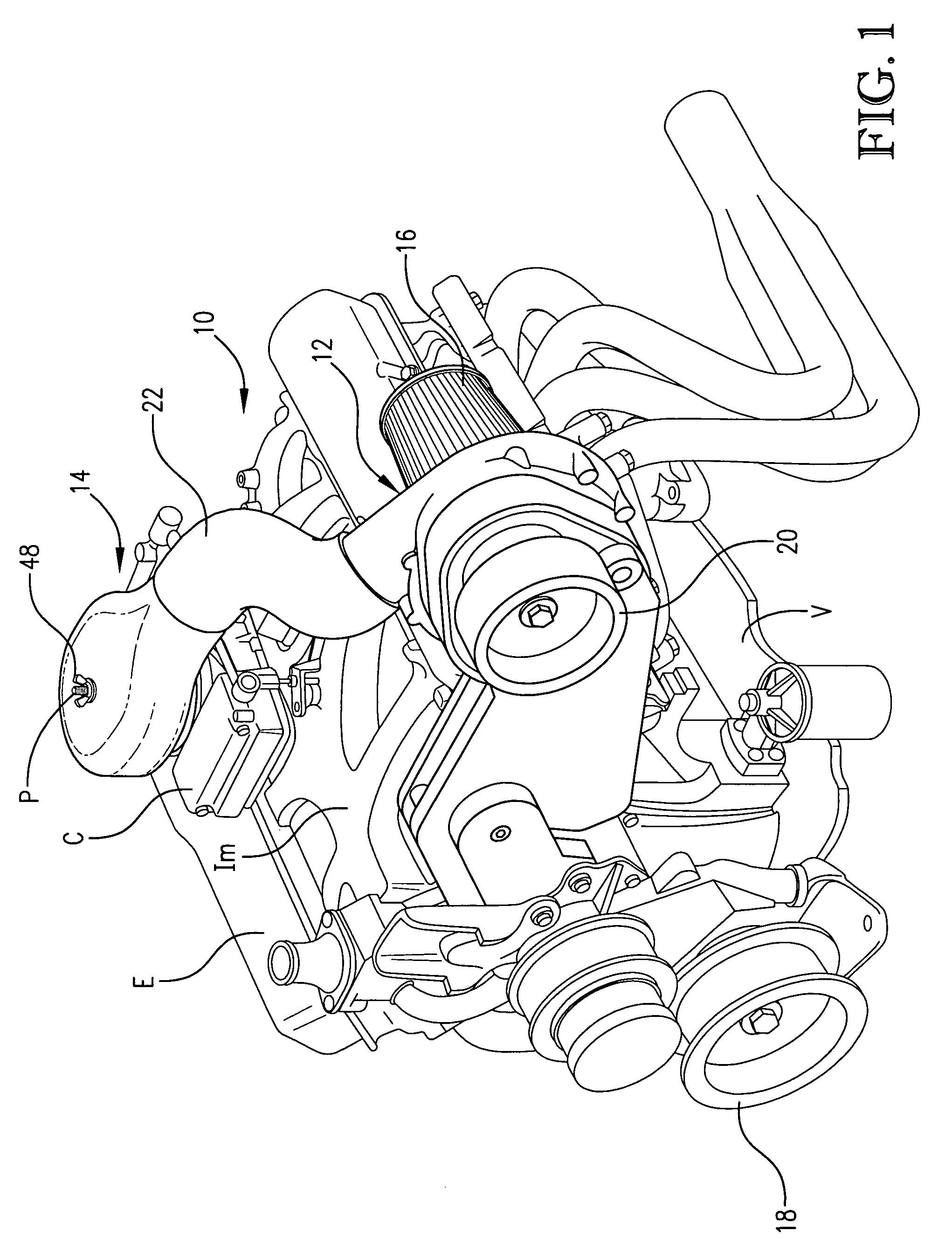
[0019]FIG. 1 illustrates a forced air induction system 10 constructed in accordance with the principles of a preferred embodiment of the present invention and configured for supplying compressed induction fluid to an internal combustion engine E for powering a vehicle V. The illustrated engine E is an eight cylinder engine that burns gasoline and utilizes a carburetor C that mixes the gasoline with the induction fluid and delivers the mixture through an intake manifold IM to the corresponding cylinders for combustion therein. The illustrated carburetor C is a four-barreled carburetor; however, any suitable carburetor could be utilized. While it is important that the engine utilizes a carburetor, the engine could be otherwise variously configured to suit the selected application. Although the principles of the present invention are particularly well suited for engines used to power land vehicles, the inventive technology could equally be applied to engines used to power other types o...


PUM

PropertyMeasurementUnit
pressureaaaaaaaaaa
Pressureaaaaaaaaaa
circumferenceaaaaaaaaaa

Abstract

A forced air induction system (10) constructed in accordance with the principles of a preferred embodiment of the present invention and configured for supplying compressed induction fluid to an internal combustion engine (E) for powering a vehicle (V) is disclosed. The illustrated forced air induction system (10) broadly includes a blower (12) for compressing induction fluid for the engine (E) and an improved carburetor hat (14) in communication with the blower (12) for delivering the compressed induction fluid to the carburetor (C). The illustrated blower (12) is a centrifugal supercharger. The illustrated carburetor hat (14) defines a neck section (26), a throat section (28), and an internal chamber (30) disposed between the neck and throat sections (26,28). The improved carburetor hat (14) is configured to prevent, or at least greatly reduce, the occurrence of thrust and stack up of induction fluid within the chamber (30) and in this regard includes an air-diffuser vane (36) disposed within the chamber (30) so that induction fluid flowing from the inlet (32) must travel around the vane (36) to reach the outlet (34).

Description

BACKGROUND OF THE INVENTION[0001]1. Field of the Invention[0002]The present invention relates generally to equipment for inducing air into an engine, such as an internal combustion engine used to power a vehicle. More specifically, the present invention concerns a carburetor hat for a forced air induction system.[0003]2. Discussion of Prior Art[0004]Internal combustion engines are known in the art, such as engines used to power vehicles of various types. It is also known in the art to utilize a carburetor to mix fuel and induction fluid and deliver this mixture to the combustion chamber(s) of the engine. Prior art carburetors include one or more chambers, or “barrels,” that utilize pressure conditions therein to draw predetermined amounts of fuel and induction fluid—i.e., amounts corresponding to the variable throttle settings within the carburetor—into the barrel for mixture and delivery to the corresponding combustion chamber. Each carburetor barrel includes a venturi and a “flow ...

Claims


Application Information

Patent Timeline
Patent Type & Authority Patents(United States)
IPC IPC(8): F02B77/00F02M35/10F02M7/22
CPCF02M35/10019F02M35/10196F02M35/10262Y10S261/19Y02T10/146Y02T10/12
Inventor SPIES, CHRISTOPHER S.JONES, DANIEL W.
Owner ACCESSIBLE TECHONOLOGIES
Why Eureka
Try Eureka