Rear mounted engine design with improved maintenance access for a military vehicle

Inactive Publication Date: 2006-09-19
BAE SYSTEMS LAND & ARMAMENTS LP
View PDF17 Cites 5 Cited by
  • Summary
  • Abstract
  • Description
  • Claims
  • Application Information

AI Technical Summary

Benefits of technology

[0012]An advantage of the present invention is that the positioning and orientation of the engine reduces space requirements.
[0013]Another advantage of the present invention is that the crew of the vehicle is isolated from the engine, which is particularly important in view of the presence of high speed turbine components.
[0014]A still further a

Problems solved by technology

The frontal location exposes the engine to greater hazards, and exposes the crew of the vehicle to the noise and exhaust of the engine.
Because of the need for at least som

Method used


Image

  • Rear mounted engine design with improved maintenance access for a military vehicle
  • Rear mounted engine design with improved maintenance access for a military vehicle
  • Rear mounted engine design with improved maintenance access for a military vehicle

Examples


Example

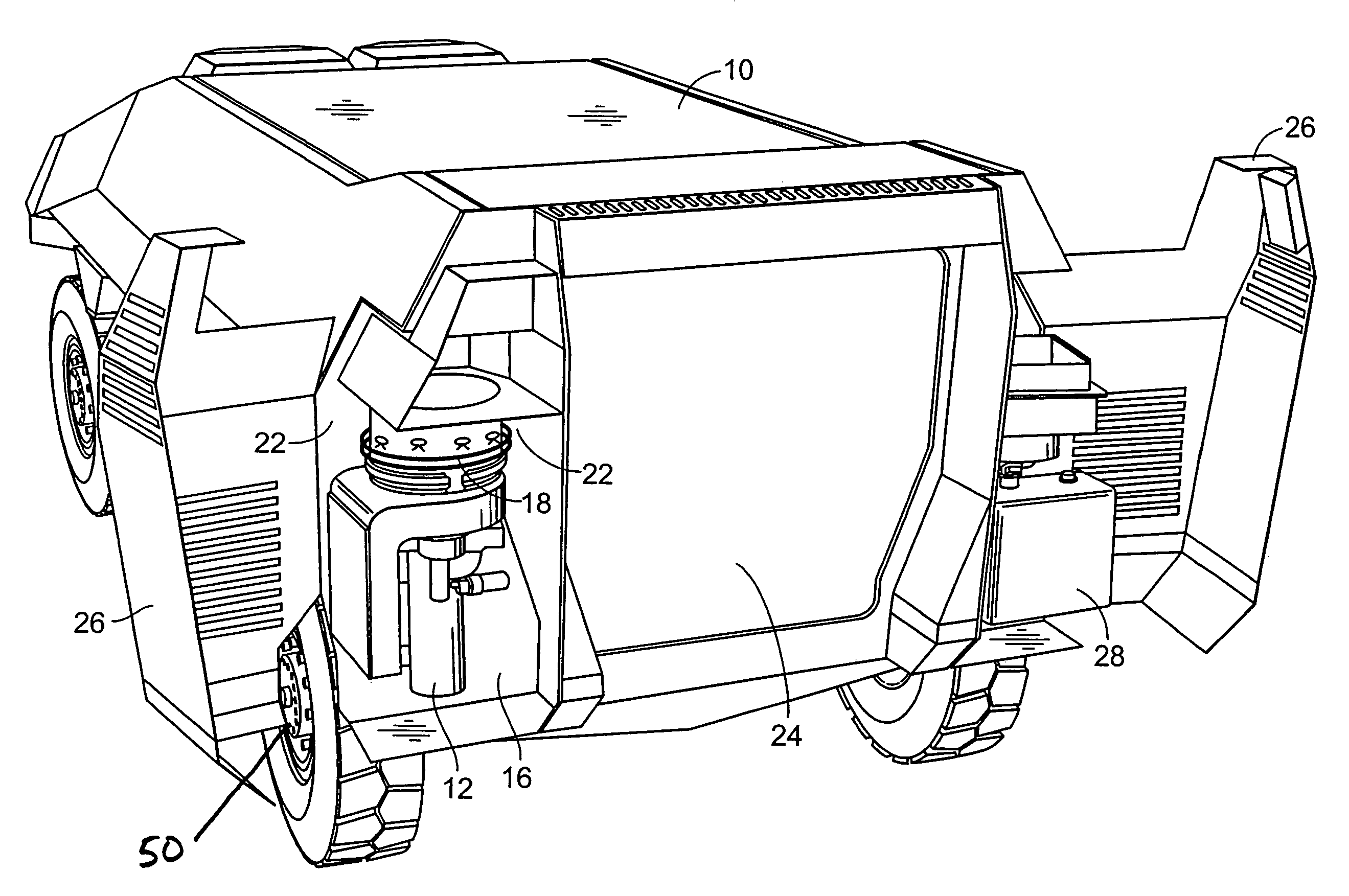
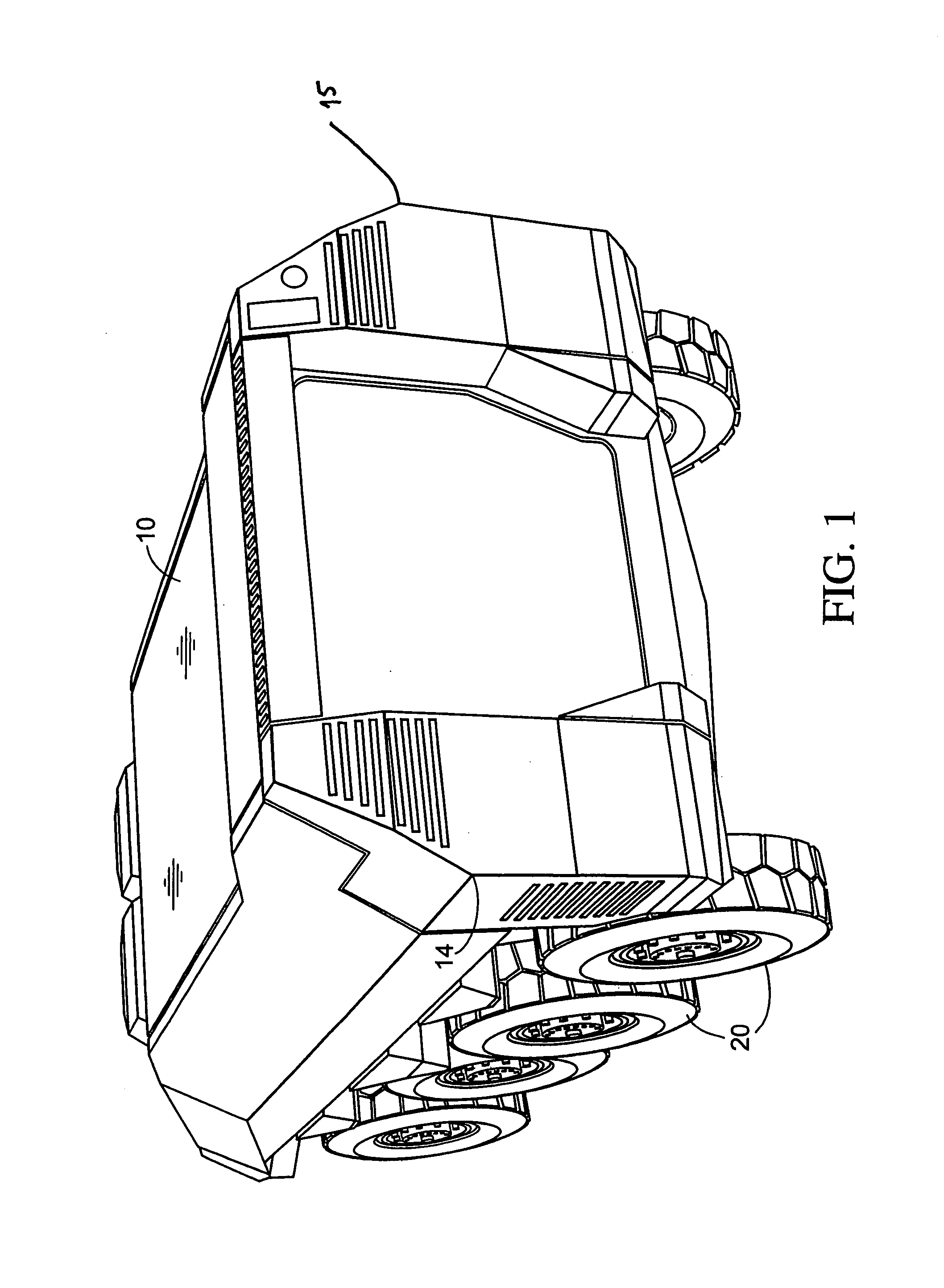
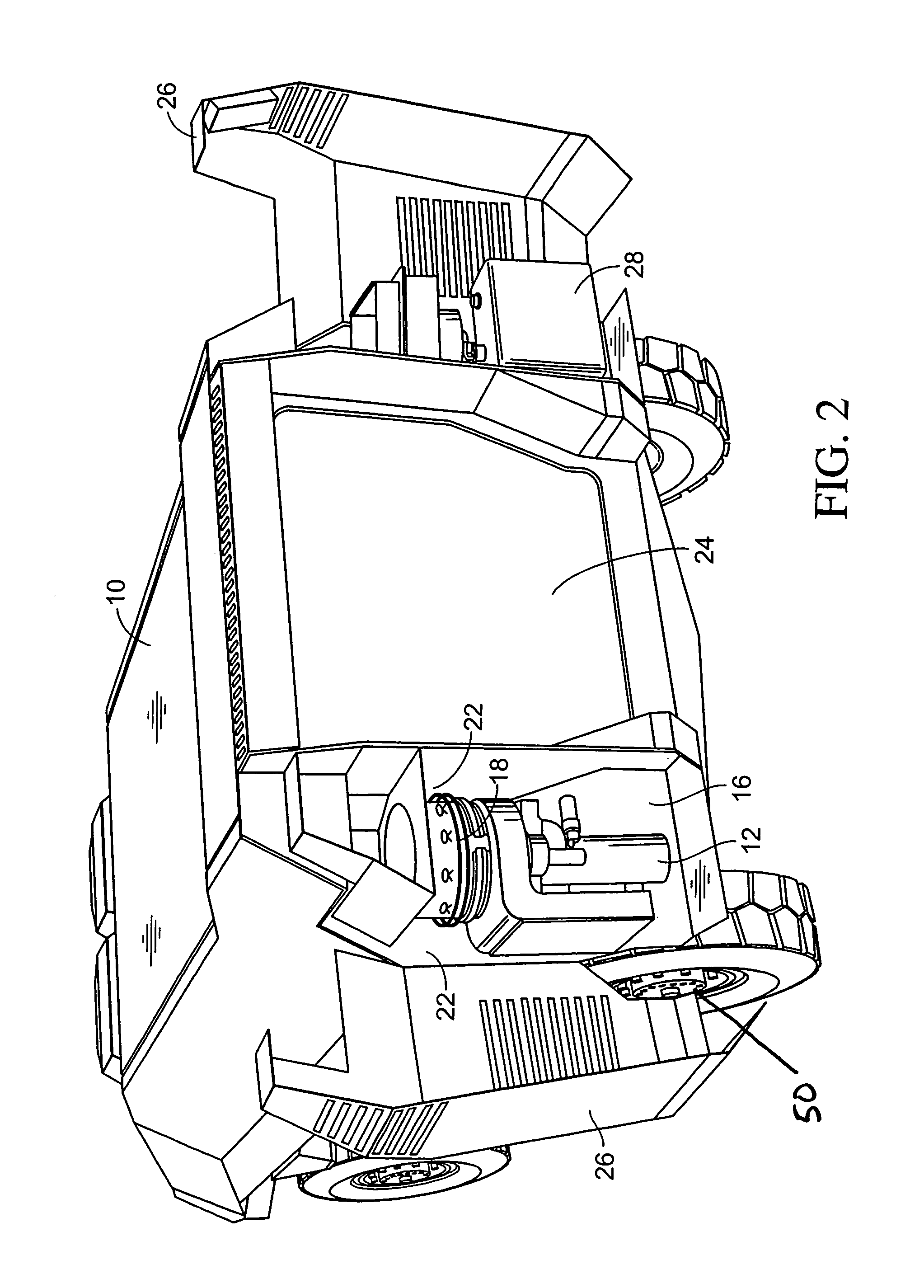
[0018]The present invention is a military vehicle 10 as illustrated in FIGS. 1 and 2 with a turbine engine 12 mounted on a first rear corner 14 of the vehicle. The turbine engine 12 is installed in an engine compartment 16. The engine 12 is installed at the rear of the vehicle 10 to provide the engine 12 with more protection than is available in a forward engine scheme, and to shield the crew from the noise, heat, exhaust, and moving parts of the engine 12.

[0019]The turbine engine 12 is oriented vertically, in order to reduce the critical space requirement. The turbine engine 12 powers an electrical generator 18 that is in communication with one or more electric drive motors schematically illustrated at 50 via a power cable. The electric drive motors of course drive the wheels 20 of the vehicle 10.

[0020]The engine compartment 16 is defined by a hull wall 22 that is open to both a lateral side and a rear side. This arrangement isolates the engine 12 from the personnel area 24 of the ...


PUM


Abstract

A military vehicle with a turbine engine mounted on an outer rear corner of the vehicle, with the engine being installed in a vertical orientation in order to save critical space. The vehicle is provided with access hatches which enable operators to easily work on the engine and related power generation components. The positioning of the engine allows the crew of the vehicle to be shielded from the heat, noise, and exhaust of the engine. The rear positioning of the engine also provides improved survivability of the engine, as well as a reduced heat signature for the vehicle. Finally, the unique engine placement provides easy access for maintenance and removal of components or component modules.

Description

BACKGROUND OF THE INVENTION[0001]1. Field of the Invention[0002]The present invention relates generally to military vehicles, and more particularly is a vehicle with a vertically mounted turbine engine situated at the rear end of the vehicle.[0003]2. Description of the Prior Art[0004]Current art vehicles most often have a front end, horizontally mounted engine. The frontal location exposes the engine to greater hazards, and exposes the crew of the vehicle to the noise and exhaust of the engine. To work on the engine, access is gained through an access hatch in the top of the vehicle. The operator therefore either has to reach into the hatch and work, or hoist out the engine if large repairs are needed.[0005]In current art vehicles, the engine is mounted in the main part of the vehicle hull. This is true whether the engine is mounted in the front, back, or middle of the vehicle. Often, the operator has to enter the vehicle interior in order to perform maintenance or repairs. Because ...

Claims


Application Information

Patent Timeline
IPC IPC(8): B62D25/10
CPCB60L11/123F41H7/02B60L2270/145Y02T10/7077Y02T10/6217B60L50/61Y02T10/62Y02T10/70Y02T10/7072
Inventor ECKSTEDT, PAUL D.
Owner BAE SYSTEMS LAND & ARMAMENTS LP
Why Eureka
Try Eureka