Insulation package and use thereof

a technology of insulation packages and condensates, which is applied to aircraft parts, aircraft floors, aircraft accessories, etc., can solve the problems of increasing the condensate problems in the insulation packages, increasing the weight of the energy-efficient package, and increasing the fuel consumption of the cabin ceiling, so as to reduce the transmission of heat and/or noise, the effect of increasing the fuel consumption or dripping condensate in the aircra

Inactive Publication Date: 2006-09-19
FRAUNHOFER GESELLSCHAFT ZUR FOERDERUNG DER ANGEWANDTEN FORSCHUNG EV
View PDF9 Cites 20 Cited by
  • Summary
  • Abstract
  • Description
  • Claims
  • Application Information

AI Technical Summary

Benefits of technology

[0006]It is therefore the object of the present invention to make available an insulation package in which moisture does not accumulate and thus additional energy-inefficient weight, an increase in fuel consumption or dripping condensate in aircraft can be avoided. This object is achieved by the insulation packet to reduce the transmission of heat and / or noise between the outer skin and the cabin lining of an aircraft comprising an insulating material enclosed by an encapsulating membrane, characterized in that the encapsulating material has at least partially a water vapor diffusion equivalent air layer thickness (sd value) dependent on ambient humidity and in accordance with DIN 52615 in the dry range (3%–50% relative humidity) has a water vapor diffusion equivalent air layer thickness (sd value) of at least 0.8 m and in the humid range (50%–93% relative humidity) has a water vapor diffusion equivalent air thickness (sd value) of 0.3 m maximum as well as by its application in an aircraft with an outer skin and a cabin lining disposed parallel to the outer skin at a predetermined distance, characterized in that insulation packages are located in the space between the outer skin and the cabin lining. Advantageous further developments of the insulation package under the invention are further described.

Problems solved by technology

An encapsulating membrane of this type results in increased moisture in the insulation packages, which can lead to additional energy-inefficient weight and an increase in fuel consumption as well as condensate dripping from the cabin ceiling.
The increase in cabin air humidity planned for the future to improve the physiological air quality in aircraft will, in all probability, further increase the condensate problems in the insulation packages.

Method used


Image

  • Insulation package and use thereof
  • Insulation package and use thereof

Examples


Embodiment Construction

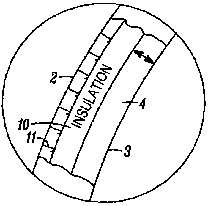
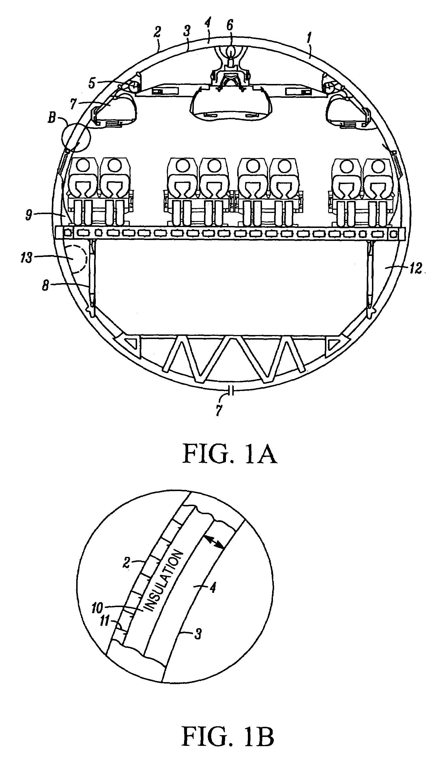
[0010]The use of insulating packages under the invention using encapsulating membranes in accordance with the invention with a variable vapor diffusion resistance brings about a reduction in the absorption of moisture at high altitude and at the same time the insulation packages can be dehumidified when the aircraft is on the ground.

[0011]The encapsulating membranes under the invention are advantageously designed in such a way that they have an sd value of about 1 m under in-flight humidity and temperature conditions. Their vapor diffusion resistance during the flight-induced condensation period is approximately as high as with the previously employed encapsulating films. Under conditions on the ground, when the insulation packages can dry out again (evaporation period), the sd value is advantageously lower by a factor of 3 than during the condensation period during flight, so that drying out is correspondingly accelerated. This can be advantageously achieved by selecting a membrane...


PUM


Abstract

An insulation package to reduce the transmission of heat and/or noise between the outer skin and the cabin lining of an aircraft composed of an insulating material enclosed by an encapsulating membrane. The encapsulating material has a vapor diffusion resistance (sd value) at least partially dependent on the ambient humidity, and for a gradient of relative humidity across the encapsulating membrane of 3% to 50% it has a vapor diffusion resistance (sd value) of at least 0.8 m and for a gradient of relative humidity across the encapsulating membrane of 50% to 93% it has a maximum vapor diffusion resistance (sd value) of 0.3 m.

Description

[0001]This application is a Continuation-In-Part of International Application No. PCT / EP02 / 12565 filed Nov. 11, 2002, currently pending.FIELD OF THE INVENTION[0002]The present invention relates to an insulation package to reduce heat transmission between the outer skin and the cabin lining of an aircraft. Such insulation packages are used to insulate heat and noise from the surrounding surfaces of the cockpit and cabin in aircraft.BACKGROUND OF THE INVENTION[0003]The insulation packages are normally attached in the area of the outer metal skin of the aircraft. They represent primary insulation, while in many cases an additional secondary insulation in the form of insulation packages is applied directly to the cabin lining.[0004]For safety reasons and for easier handling, the insulation packages consist of non-combustible and / or hard-to-ignite mats of insulating material (mostly of mineral wool) which, as with a cushion, are enclosed by an encapsulating membrane.[0005]At cruising alt...

Claims


Application Information

Patent Timeline
Patent Type & Authority Patents(United States)
IPC IPC(8): B64C1/40
CPCB64C1/40Y10T428/239
Inventor KUNZEL, HARTWIGHOLM, ANDREASGROSSKINSKY, THEO
Owner FRAUNHOFER GESELLSCHAFT ZUR FOERDERUNG DER ANGEWANDTEN FORSCHUNG EV
Why Eureka
Try Eureka