Wearable jacket having communication function, and endoscope system employing wearable jacket
a technology of communication function and wearable jacket, which is applied in the field of wearable antenna jacket, can solve the problems of difficult to insert such an endoscope in a thin, long and meandering portion, and burdensome subject observation using such an endoscop
- Summary
- Abstract
- Description
- Claims
- Application Information
AI Technical Summary
Benefits of technology
Problems solved by technology
Method used
Image
Examples
first embodiment
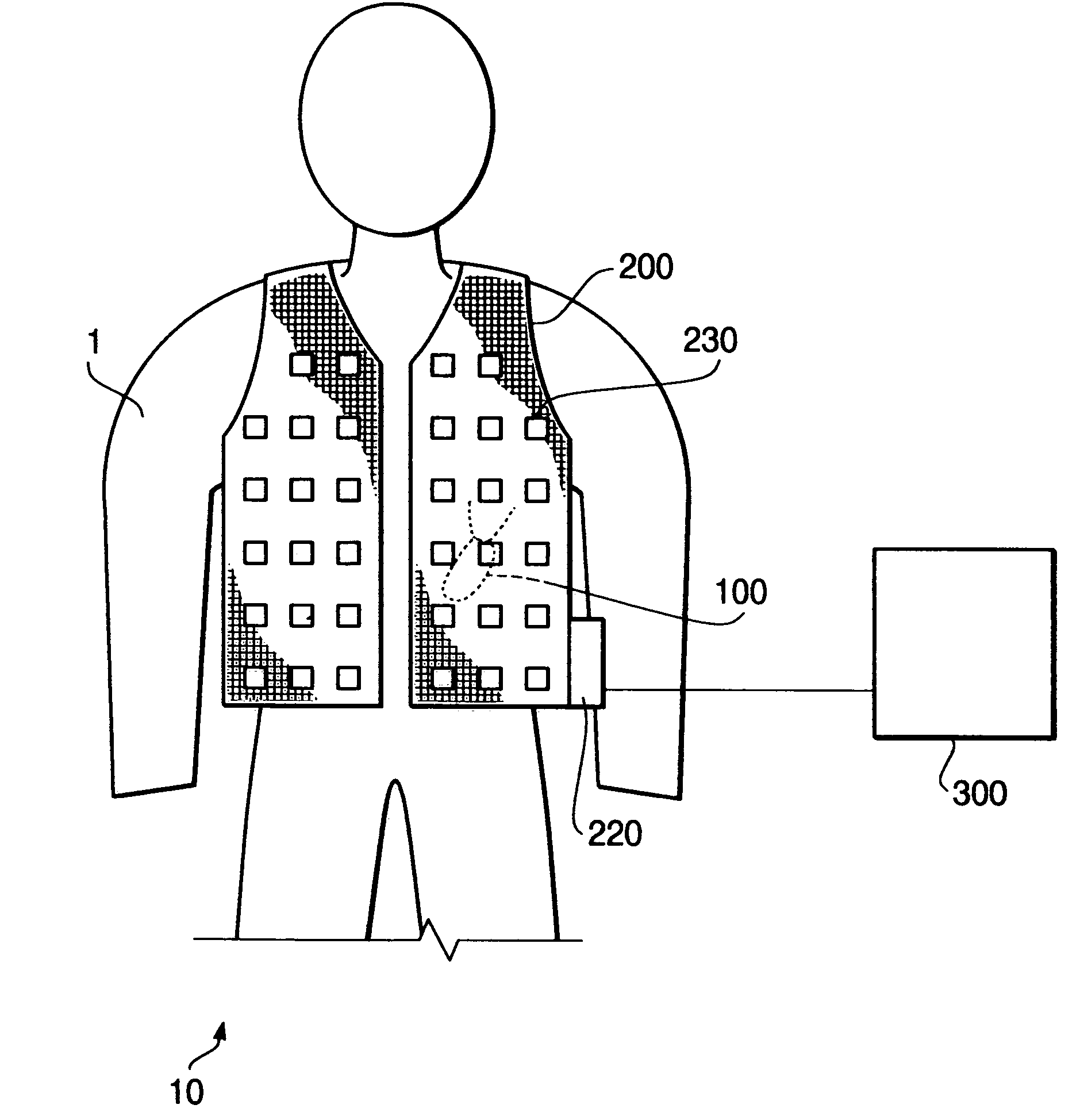
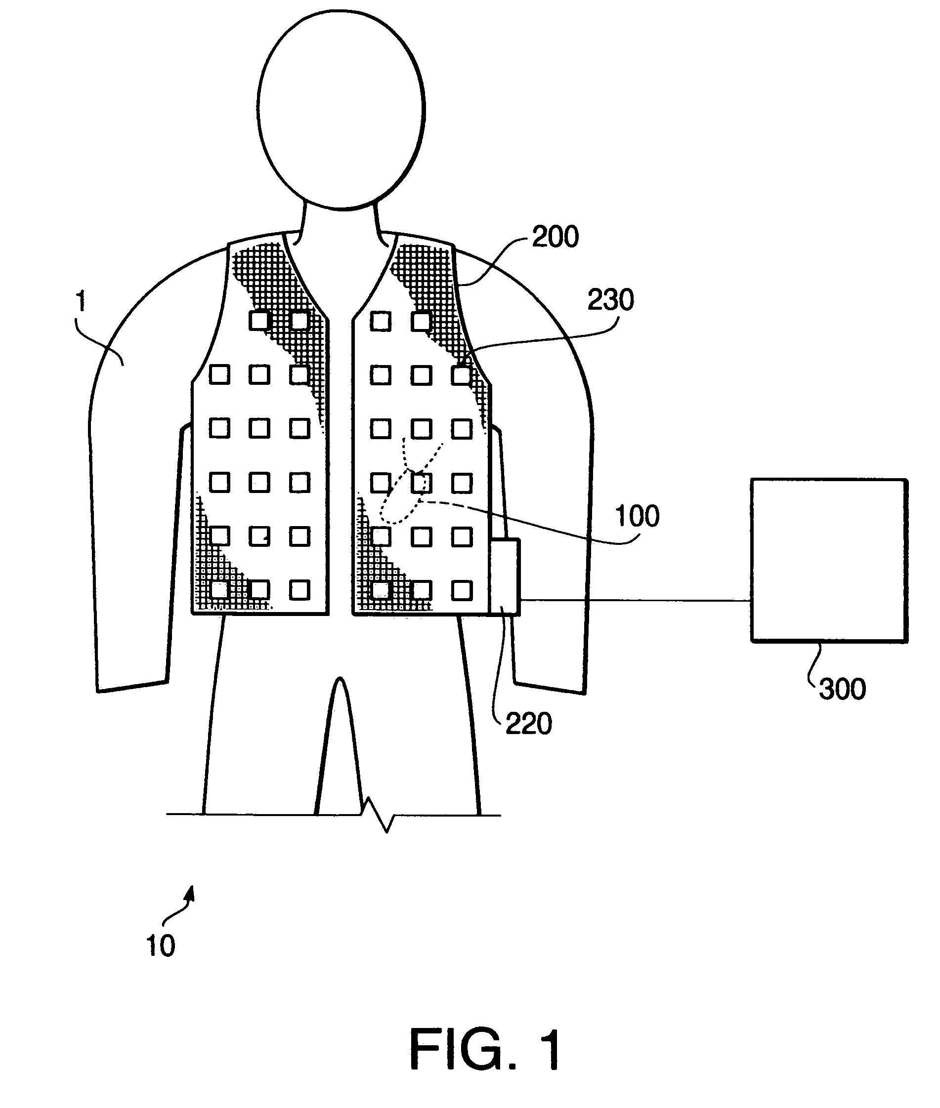
[0044]FIG. 1 schematically shows a configuration of the endoscope system 10 according to an embodiment of the invention. The endoscope system 10 is used, for example, to obtain the body functions (e.g., pulse, blood pressure, temperature etc.) and / or image information of body cavities and the like of the subject 1. Such data is used for diagnosing the subject 1.
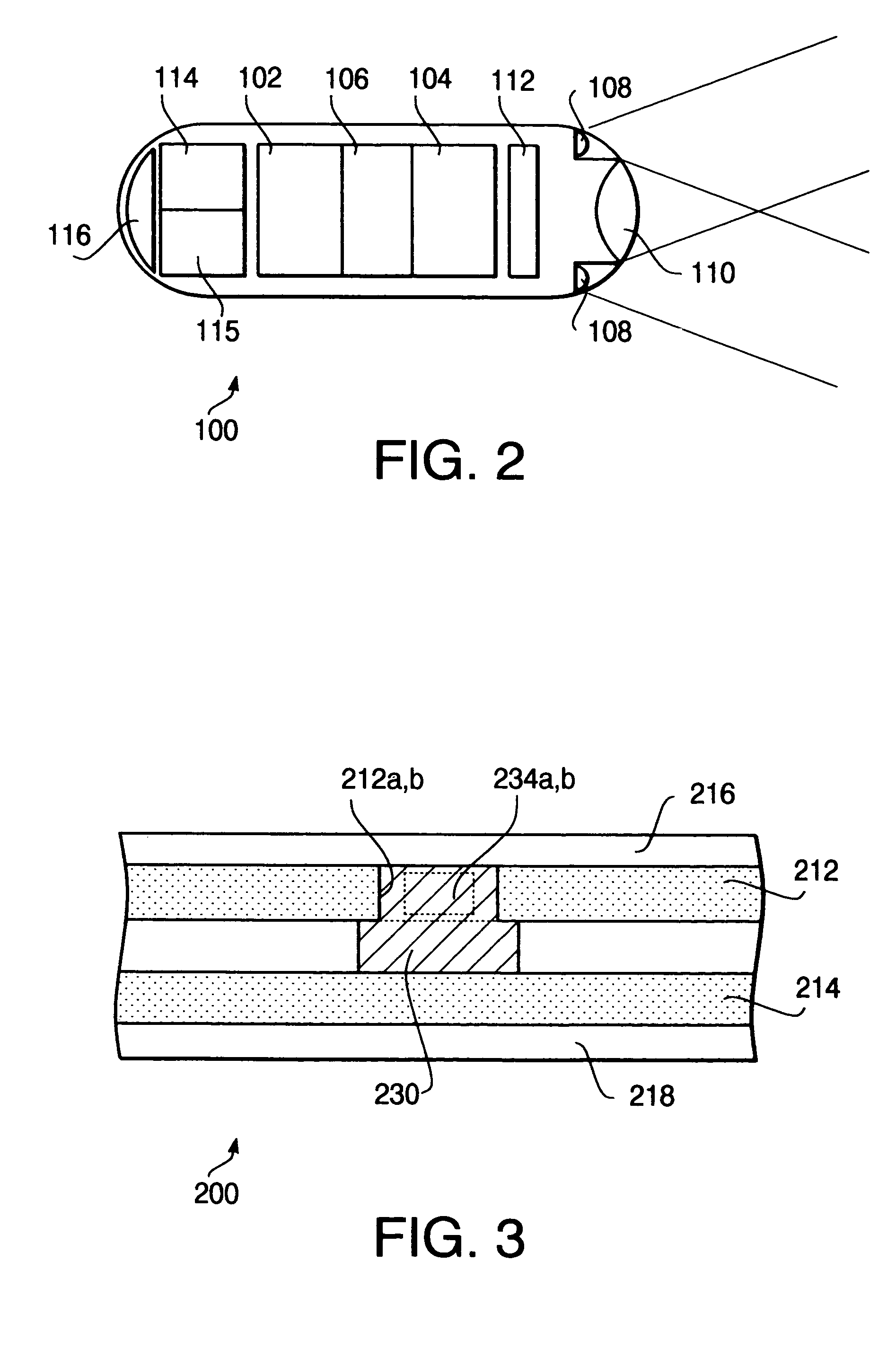
[0045]As shown in FIG. 1, the endoscope system 10 includes a capsule endoscope 100 which is inserted (swallowed) inside the subject 1, an antenna jacket 200, and a personal computer (PC) 300. The capsule endoscope 100 captures images inside the subject 1 and outputs image data by radio. The antenna jacket 200 is provided with a plurality of antennas and circuits, and receives the image data output by the capsule endoscope 100. The antenna jacket 200 transmits the obtained signal and data related to the body functions to the PC 300. The PC 300 is provided with a display, which displays the data (e.g., image data) received from...
second embodiment
[0103]FIG. 11 shows a flowchart illustrating a data obtaining procedure executed by the control unit 220 according to the second embodiment. According to the procedure shown in FIG. 7, the reception module is selected every time the obtained image and the body function data is stored in the memory 224. According to the second embodiment, the reception module is selected at every predetermined timing. In the following description on FIG. 11, the steps which are the same as those in FIG. 7 will be assigned with the same step numbers and description thereof will be omitted for the brevity.
[0104]When the power switch of the control unit 220 is ON and the ID data setting process is executed in S1, controller 221 starts a counter A (which has an initial value of zero) in S31. The counter A is referred to in S33, which will be described later. After controller 221 judges whether the power source is OFF in S2, and steps S3 and S4 are executed, the controller 221 increments the counter A by ...
third embodiment
[0110]FIG. 12 is a flowchart of the data obtaining procedure according to a third embodiment. According to the procedure shown in FIG. 12, acquisition of the image data, acquisition of the body function data and selection of the reception module are executed at different timings. It should be noted that the steps same as those in FIG. 7 or FIG. 11 will be assigned with the same step numbers and description thereof will be omitted for the brevity.
[0111]When the power switch (not shown) is turned ON and the ID data setting process is executed in S1, controller 221 starts the counters A (initial value=0) and B (initial value=0) in S31. After judgment in S2, reception module selection procedure in S3 and path determining procedure in S4 are finished, the controller 221 increments the counter A by one (S32).
[0112]When steps S5 and S6 are finished (i.e., the image signal is transmitted to the control unit 220 and stored in the memory 224), the controller 221 judges whether the value of th...
PUM
 Abstract
Description
Claims
Application Information
 - R&D
- Intellectual Property
- Life Sciences
- Materials
- Tech Scout
- Unparalleled Data Quality
- Higher Quality Content
- 60% Fewer Hallucinations
Browse by: Latest US Patents, China's latest patents, Technical Efficacy Thesaurus, Application Domain, Technology Topic, Popular Technical Reports.
© 2025 PatSnap. All rights reserved.Legal|Privacy policy|Modern Slavery Act Transparency Statement|Sitemap|About US| Contact US: help@patsnap.com


