Device and a method for an infrared image analyzing autofocus

a technology of infrared image and autofocus, which is applied in the field of infrared optical systems, can solve the problems of additional difficulties in infrared autofocus, limited light energy transmitted through the objective, and the limitation device is the detecting unit and its performance and efficiency characteristics, so as to improve the quality of the focused image and enhance the focusing performance of the apparatus

Inactive Publication Date: 2006-09-19
FLIR SYST AB
View PDF20 Cites 33 Cited by
  • Summary
  • Abstract
  • Description
  • Claims
  • Application Information

AI Technical Summary

Benefits of technology

[0012]By means of the invention is it possible to choose an area of the image detection means other than a central area to focus on. Such an area subjected to analysis would enable a selection of the most interesting and informative parts of the image to be accomplished. A deliberate choice in this described way, could make a procedure of focusing possible on the most rewarding area of the detected image area and thus enhance the focusing performance of the apparatus and improve the quality of the focused image.

Problems solved by technology

The limited amount of light energy transmitted through the objective constitutes additional difficulties to infrared autofocuses in comparison with visible light autofocuses.
In infrared optical systems like the above mentioned, the limiting device is the detecting unit and its performance and efficiency characteristics.
Due to the above mentioned additional difficulties associated with infrared autofocusing apparatus, the complexity of prior known systems has increased to an unacceptable level when attempts have been made at managing the low energy level of infrared light.
The major problem related to such infrared systems is the low f-number.
Processing capacity in such objectives is limited due to the additional costs associated with higher processing capacity and the cost will finally fall on the end consumer.
Until today, no successful solutions of this problem have been made.

Method used


Image

  • Device and a method for an infrared image analyzing autofocus
  • Device and a method for an infrared image analyzing autofocus
  • Device and a method for an infrared image analyzing autofocus

Examples


first embodiment

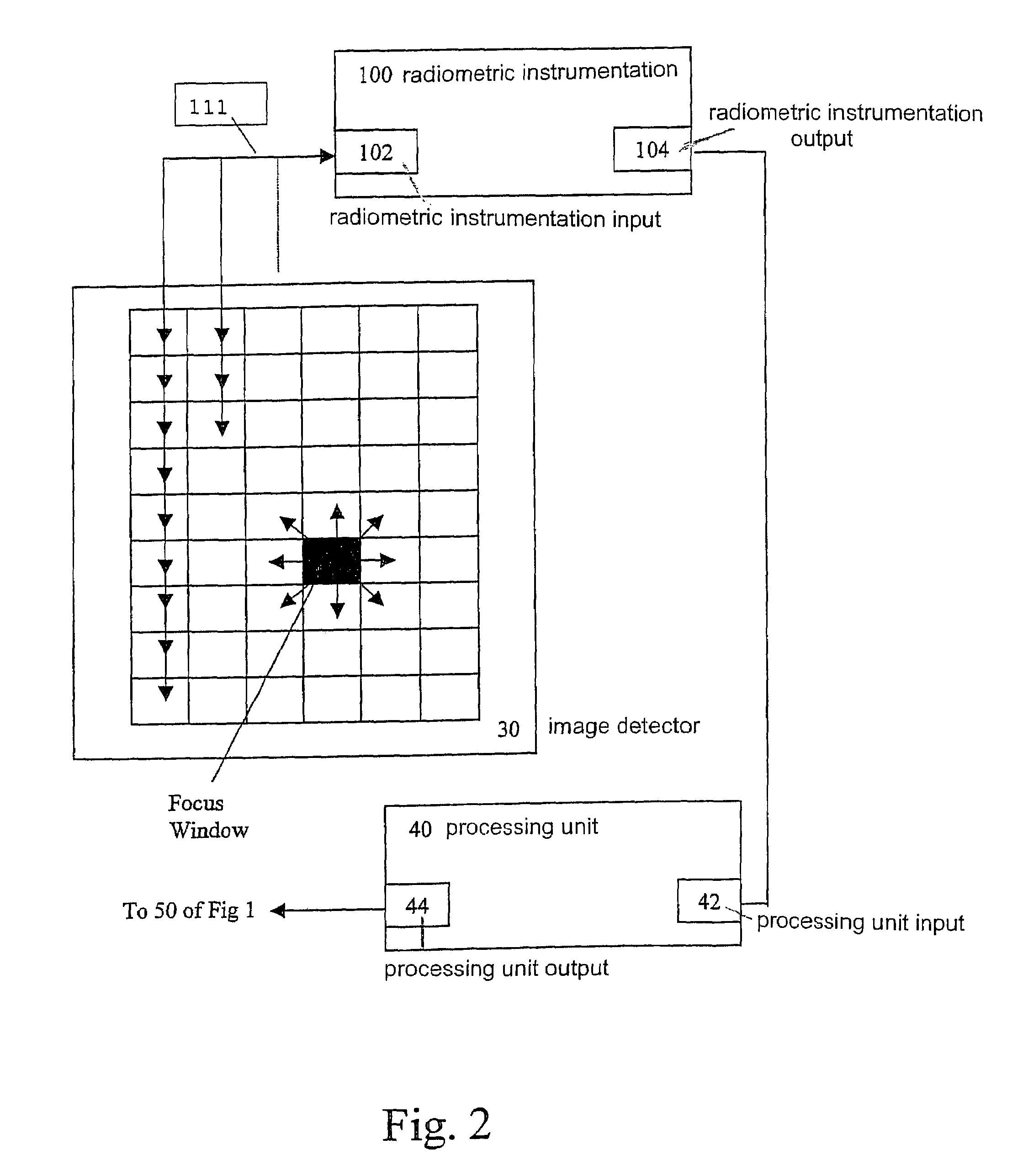
[0037]In a first embodiment, shown in FIG. 2, the focusing is carried out through image analysis of one single pixel (denoted focus window in FIG. 2) within the detector array 30. The particular pixel to be image analysed and thus focused on is searched among all pixels of the detector array 30 and is chosen due to its thermal properties. The pixel is distinguished from all other pixels of the detector array because of its extreme temperature value. The pixel subjected to focusing may be either the coldest or the warmest. Such an approach requires a bi-directional radiometer connection 111 in connection with each pixel of the detector array 30 and with an input 102 of a radiometric instrumentation 100 from which output 104 image signals with radiometric data are delivered to the input 42 of the processing unit 40. Compilation, processing and analysis of received data is performed within the processing unit 40, first with a coarse process using a low pass filtering, and the result of...

second embodiment

[0039]Operation would be a convenient and efficient method for use when detection of humans is desirable, for example during rescue actions or for various surveillance purposes. Especially in combination with some kind of scanning equipment, large areas could efficiently be searched and surveyed from above by a minimum of personnel.

[0040]In an alternative second embodiment, also with reference to FIG. 3, the focus window is chosen based on predetermined threshold temperature values. These temperature values can be manually or automatically inserted parameters of the processing unit 40. One operative example of an application of this alternative embodiment could be related to thermal industrial processes. This often results in an image sub-area of pixels. The processing unit 40 then makes an iteration in order to derive the position of the moving means 50 giving the best adaptation to the focus function within the sub-area.

[0041]In some of these thermal industrial processes, it may ...


PUM


Abstract

An apparatus and a method is introduced by which infrared image analysing automatic focusing is made possible. The invention among others comprises a focus function to be used by a search operation in order to control a moving means (50) adjusting a focusing optical convergence arrangement (20). Usage of the invention enables a fast and efficient way of obtaining a focused image although the infrared optical system is a difficult system and a not particularly rewarding technique in the past.

Description

TECHNICAL FIELD OF THE INVENTION[0001]The present invention generally relates to the field of infrared optical systems and especially to the apparatus and methods required for automatic focusing on viewed objects.BACKGROUND OF THE INVENTION[0002]When infrared optical systems are taken into consideration, a number of physical properties in connection with this kind of infrared technology must be regarded. The limited amount of light energy transmitted through the objective constitutes additional difficulties to infrared autofocuses in comparison with visible light autofocuses. In infrared optical systems like the above mentioned, the limiting device is the detecting unit and its performance and efficiency characteristics. This is one of the reasons explaining that the attempts at constructing automatic infrared image analysing focuses have not succeeded in the past.[0003]An article of Frank R. Boddeke et al. in the publication Bioimaging, 2, 193–203, (1994) discloses an algorithm for...

Claims


Application Information

Patent Timeline
Patent Type & Authority Patents(United States)
IPC IPC(8): H04N5/232G02B7/28G01S5/14G02B7/36H04N5/225H04N5/33H04N7/18
CPCG02B7/365H04N5/33H04N5/23293H04N23/673H04N23/633
Inventor HELLSTRAND, MAGNUS
Owner FLIR SYST AB
Why Eureka
Try Eureka