Rotation and translation measurement

Inactive Publication Date: 2006-09-19
EXCEL PRECISION
View PDF10 Cites 10 Cited by
  • Summary
  • Abstract
  • Description
  • Claims
  • Application Information

AI Technical Summary

Benefits of technology

[0016]An advantage of the present invention is that it provides highly desirable non-contact position determination, based on its use of optical principles. Further, due to its ability to employ lasers as a light source, the invention may be used for measurement targets ranging from small to quite large and at distances ranging from near to quite remote.
[0017]Another advantage of the invention is that it permits measurement of combinations of positional characteristics which have previously been difficult to attain with a limited component count. For example, using two parallel optical channels it can measure target translation or straightness in a perpendicular x-y plane as well as target roll in the x-y plane. The invention is thus effectively able to measure three axes or degrees of freedom with only two sensors. Still additional sensors can also be added to provide yet further capability
[0018]Another advantage of the invention is that its speed of measurement is considerably less limited than is the case for relative type measurement systems. The invention can accurately measure position when a target is at rest, i.e., zero speed, and also when a target is moving quite s

Problems solved by technology

However, particularly as modem applications become increasingly complex, the often conflicting goals of measurement accuracy and manufacturing speed remain ones where many seek further improvement.
Of course, and as often is the case, movement may be limited to only some of or may not be of interest in only some of these degrees of freedom, but accurate and fast measurement is still often a daunting task.
Further, if displacement occurs too slow or too fast even these techniques will fail.
Unfortunately, the simple position determining system of FIG. 1 can only provide positional information about three degrees of freedom for the movement stage 12.
Doing this would thu

Method used


Image

  • Rotation and translation measurement
  • Rotation and translation measurement
  • Rotation and translation measurement

Examples


Embodiment Construction

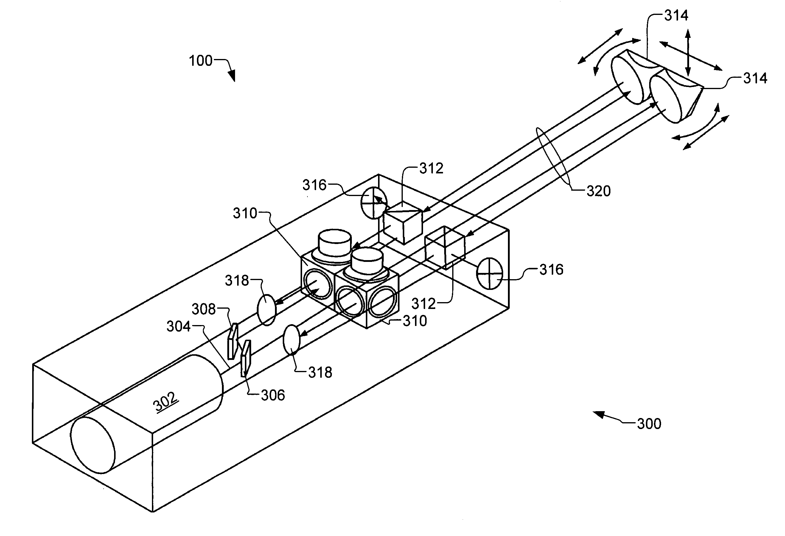
[0032]A preferred embodiment of the present invention is a position determining system (hereinafter “PDS”). As illustrated in the various drawings herein, and particularly in the views of FIGS. 2 and 5, the inventive device is depicted by the general reference character 100. Where appropriate, reference numbers are reused in the figures.

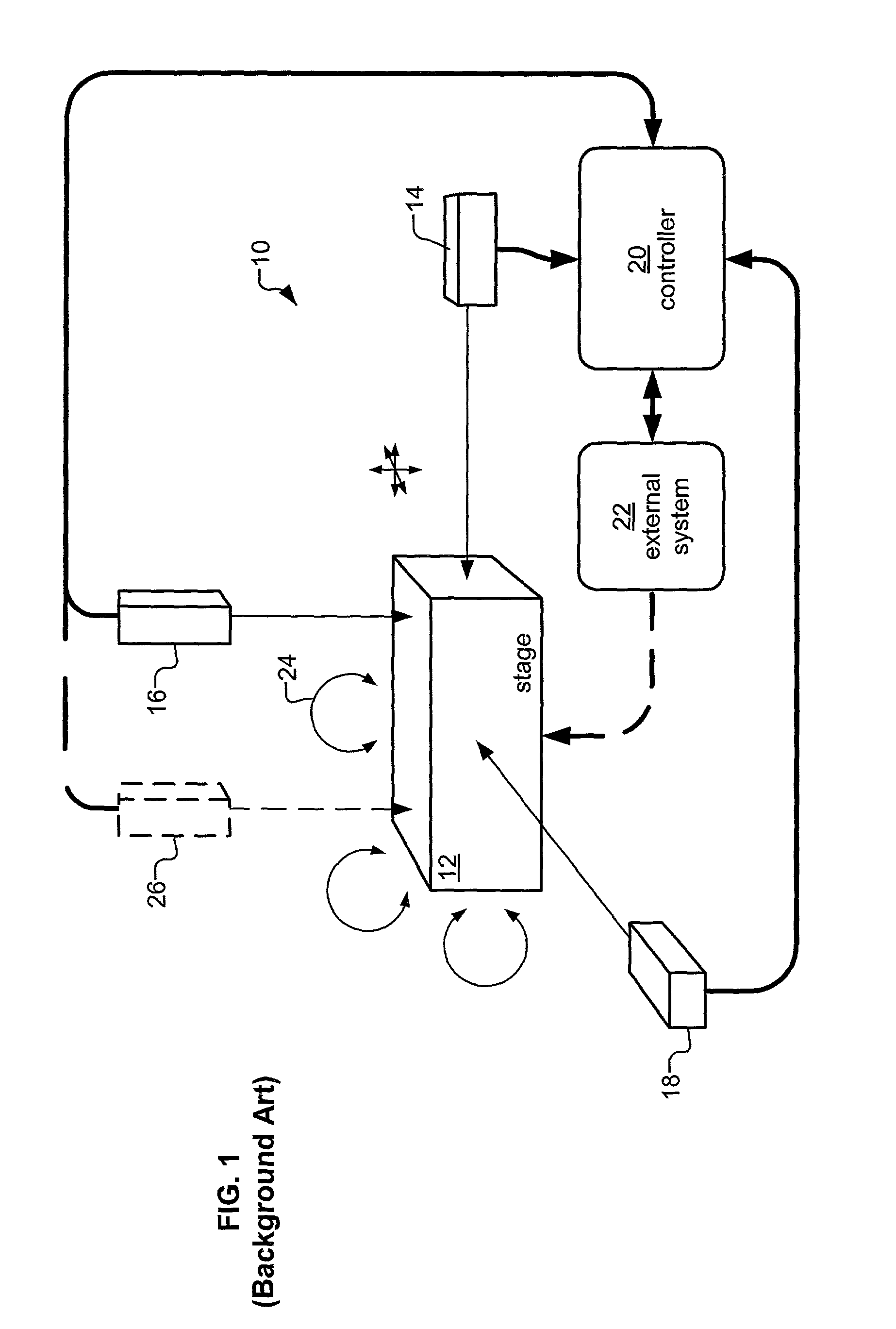
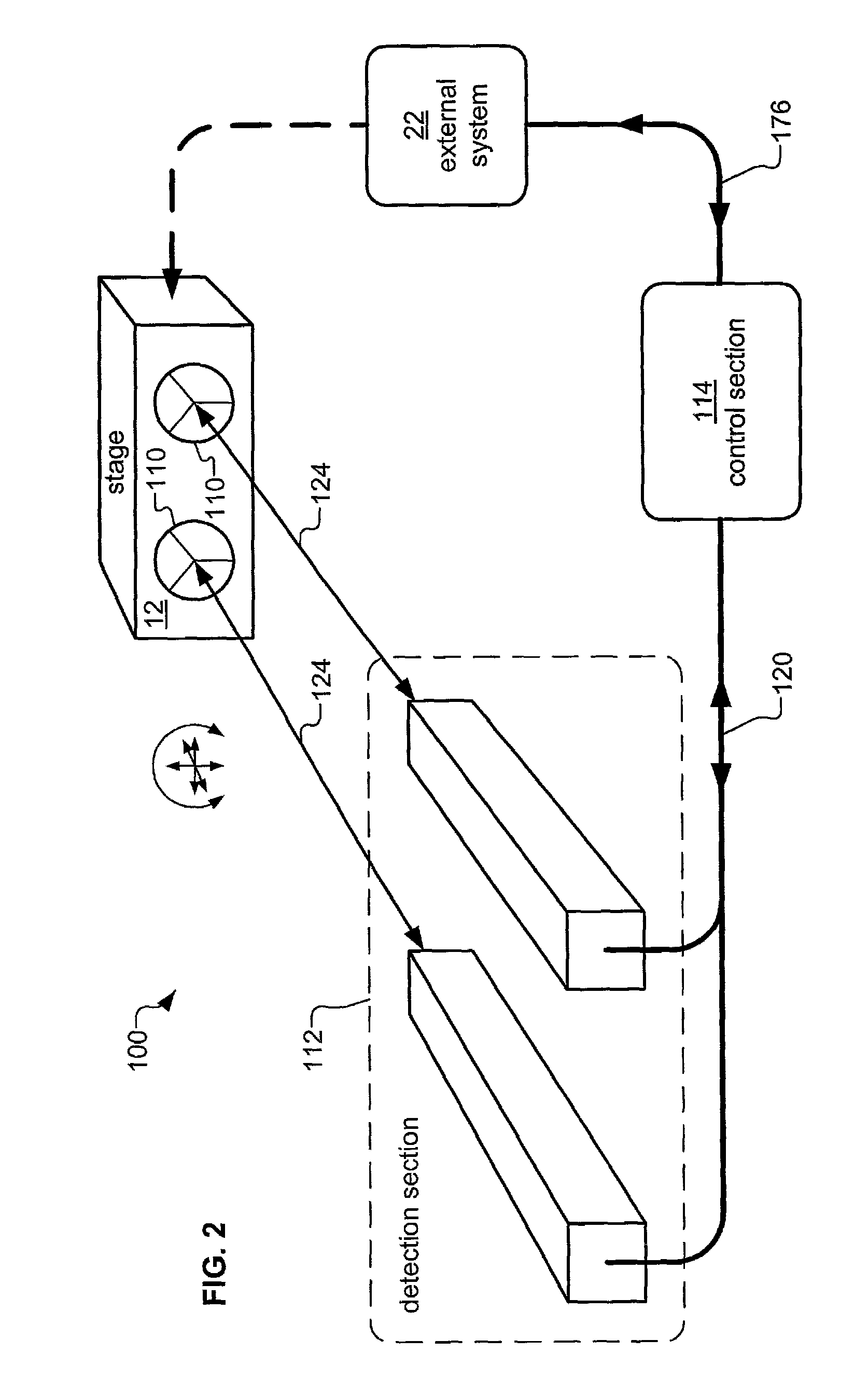
[0033]FIG. 2 depicts a preferred embodiment of the inventive PDS 100 in a generic usage scenario for determining positional information about a typical movement stage 12, such as that of FIG. 1 (background art). Retroreflective targets 110 are mounted on the movement stage 12; a detection section 112 is provided to optically sense information about the retroreflective targets 110; and a control section 114 is provided to control the operation of the PDS 100 and to communicate with an external system 22. The movement stage 12 and the external system 22 are not formally parts of the inventive PDS 100. As discussed with respect to FIG. 1 (background art...


PUM


Abstract

A position determining system (PDS)(100) or multiple parameters measurement system (MPMS)(300) particularly useful for translation and rotation measurement of objects having up to five degrees of freedom. A light source (122, 302) provides light beams (124, 304) into at least two channels. Each channel may include an interferometer (310), reflective target (110, 314), beam splitter (128, 312), detector (132, 316), and receiver (318). In concert, the detectors (132, 316) sense horizontal, vertical, and roll position and the receivers (318) sense longitudinal and yaw position change. Optionally, modulation can be imposed on the light beams (124, 304) and phase-sensitive synchronous demodulation used to enhance accuracy.

Description

CROSS-REFERENCE TO RELATED APPLICATIONS[0001]This application is a continuation-in-part of U.S. application Ser. No. 09 / 434,100 filed Nov. 5, 1999, now U.S. Pat. No. 6,316,779 which is a continuation-in-part of U.S. application Ser. No. 08 / 812,998 filed Mar. 4, 1997, now U.S. Pat. No. 5,991,112 issued Nov. 23, 1999.TECHNICAL FIELD[0002]The present invention relates generally to the field of optical measurement, and more particularly to accurately detecting positional characteristics of a fixed or moving measurement target. It is anticipated that primary applications of the present invention will be in manufacturing of highly precise assemblies and in industrial and laboratory processes requiring high precision position detection and control.BACKGROUND ART[0003]Many present industries and fields of research are encountering a need for faster and more accurate position and movement determination. For example, in semiconductor fabrication and disk drive assembly the capacity of the ult...

Claims


Application Information

Patent Timeline
IPC IPC(8): G01B11/02G11B5/55G11B21/02G11B21/08G11B21/10
CPCG11B5/5552G11B21/02G11B21/08G01B9/02019G01B9/02045G01B9/02027G11B21/106G01B2290/15
Inventor TSAI, JOHN C.
Owner EXCEL PRECISION
Why Eureka
Try Eureka