Small imaging lens and imaging apparatus

a technology of which is applied in the field of small imaging lens and imaging apparatus, can solve the problems of difficult aberration correction and difficulty in obtaining and achieve the effect of small size and good image-side telecentric characteristics

Inactive Publication Date: 2006-09-19
KONICA MINOLTA OPTO
View PDF4 Cites 40 Cited by
  • Summary
  • Abstract
  • Description
  • Claims
  • Application Information

AI Technical Summary

Benefits of technology

[0006]The present invention has been made in consideration of the above problems, and has as its object to provide a five element/four gro...

Problems solved by technology

However, as an imaging lens having such an arrangement, i.e., an arrangement in which a positive lens group having strong refracting power is placed near an aperture stop nearest to the object side, is reduced in total length, the exit pupil of the whole imagin...

Method used


Image

  • Small imaging lens and imaging apparatus
  • Small imaging lens and imaging apparatus
  • Small imaging lens and imaging apparatus

Examples


first embodiment

(First Embodiment)

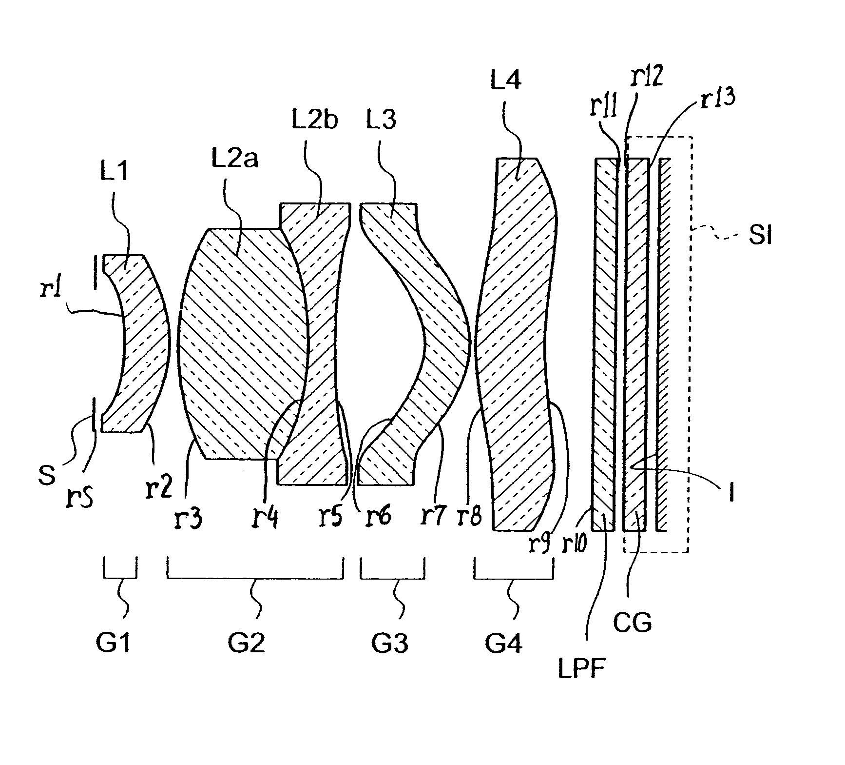
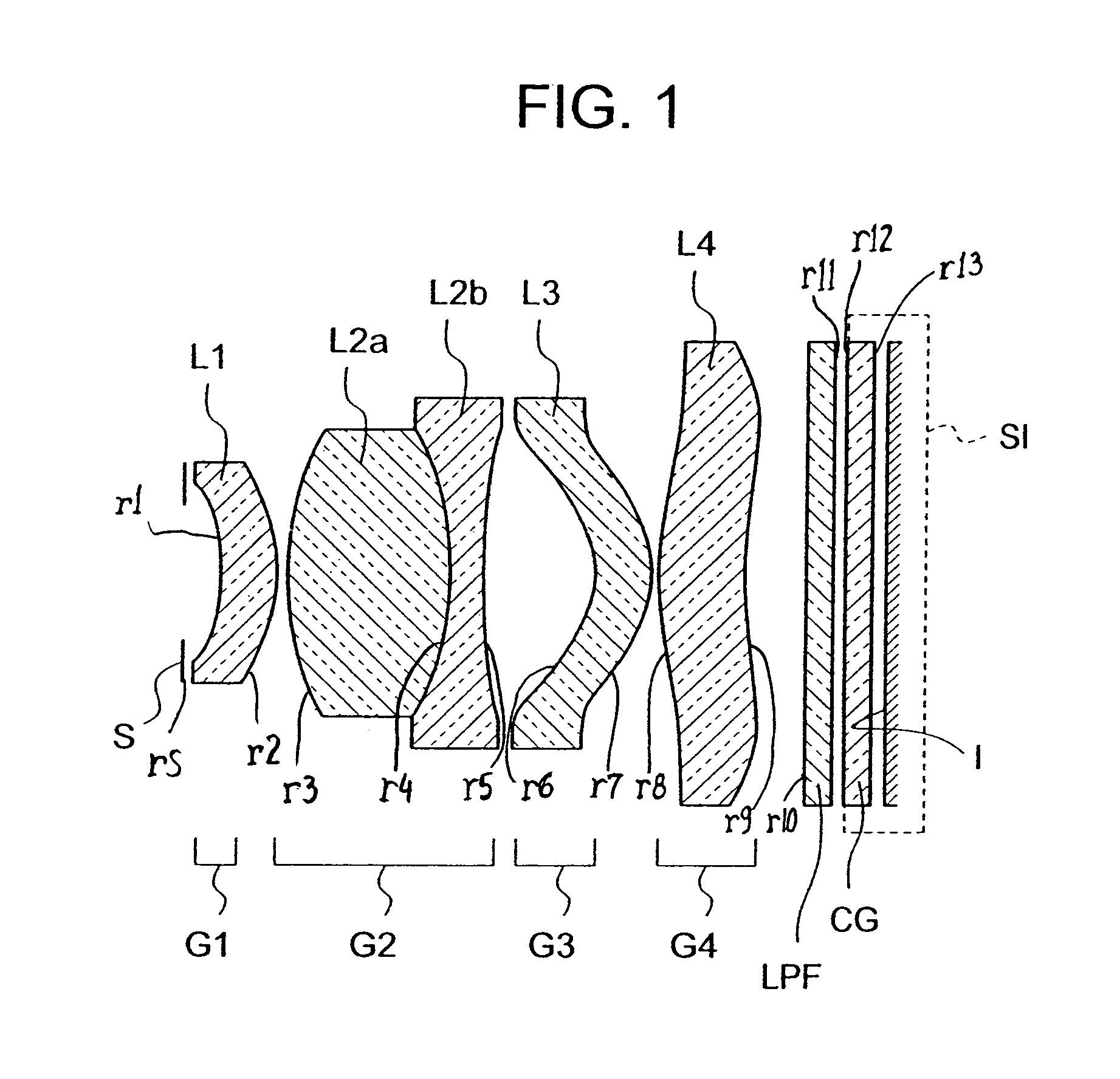
[0065]FIG. 1 is a sectional view of an imaging apparatus including an imaging lens according to the first embodiment of the present invention which is taken along the optical axis direction. Referring to FIG. 1, the imaging lens sequentially includes, from the object side, an aperture stop S, first lens group G1, second lens group G2, third lens group G3, and fourth lens group G4. The first lens group G1 is comprised of only a first lens L1 having a meniscus shape with its concave surface facing the object side. The second lens group G2 has positive refracting power as a whole, and sequentially includes, from the object side, a 2-1st lens L2a having positive refracting power and a 2-2nd lens L2b cemented to the 2-1st lens L2a and having negative refracting power. The third lens group G3 is comprised of only a third lens L3 having a meniscus shape with its concave surface facing the object side. The fourth lens group G4 is comprised of only a fourth lens L4.

[0066]Th...

second embodiment

(Second Embodiment)

[0081]FIG. 3 is a sectional view of an imaging apparatus including an imaging lens according to the second embodiment of the present invention which is taken along the optical axis direction. Referring to FIG. 3, the imaging lens sequentially includes, from the object side, an aperture stop S, first lens group G1, second lens group G2, third lens group G3, and fourth lens group G4. The first lens group G1 is comprised of only a first lens L1 having a meniscus shape with its concave surface facing the object side. The second lens group G2 has positive refracting power as a whole, and sequentially includes, from the object side, a 2-1st lens L2a having positive refracting power and a 2-2nd lens L2b cemented to the 2-1st lens L2a and having negative refracting power. The third lens group G3 is comprised of only a third lens L3 having a meniscus shape with its concave surface facing the object side. The fourth lens group G4 is comprised of only a fourth lens L4.

[0082]...

third embodiment

(Third Embodiment)

[0096]FIG. 5 is a sectional view of an imaging apparatus including an imaging lens according to the third embodiment of the present invention which is taken along the optical axis direction. Referring to FIG. 5, the imaging lens sequentially includes, from the object side, an aperture stop S, first lens group G1, second lens group G2, third lens group G3, and fourth lens group G4. The first lens group G1 is comprised of only a first lens L1 having a meniscus shape with its concave surface facing the object side. The second lens group G2 has positive refracting power as a whole, and sequentially includes, from the object side, a 2-1st lens L2a having positive refracting power and a 2-2nd lens L2b having negative refracting power. The third lens group G3 is comprised of only a third lens L3 having a meniscus shape with its concave surface facing the object side. The fourth lens group G4 is comprised of only a fourth lens L4.

[0097]The image sensing device is comprised...


PUM


Abstract

An imaging lens includes sequentially, from an object side, a first lens group, a second lens group, a third lens group, and a fourth lens group. The first lens group includes only a first lens having a meniscus shape with a concave surface facing the object side. The second lens group has positive refracting power as a whole and includes sequentially, from the object side, a second-first lens having positive refracting power and a second-second lens cemented to or separated from the second-first lens and having negative refracting power. The third lens group includes only a third lens having a meniscus shape with a concave surface facing the object side. The fourth lens group includes only a fourth lens.

Description

BACKGROUND OF THE INVENTION[0001]1. Field of the Invention[0002]The present invention relates to a small imaging lens for forming an optical image on a solid-state image sensing device such as a CCD type image sensor or CMOS type image sensor, and an imaging apparatus using the same.[0003]2. Description of the Related Art[0004]Imaging apparatuses using solid-state image sensing devices such as CCD (Charge-Coupled Device) type image sensors and CMOS (Complementary Metal-Oxide Semiconductor) type image sensors include digital still cameras, digital video cameras, and the like. Imaging apparatuses using such solid-state image sensing devices are suitable for miniaturization, and hence have recently been mounted in compact information terminals such as cellular phone sets. With increases in the miniaturization and pixel density of solid-state image sensing devices, demands have arisen for smaller and higher-performance imaging lenses to be mounted in these imaging apparatuses. As imagin...

Claims


Application Information

Patent Timeline
IPC IPC(8): G02B13/18G02B13/04G02B3/02G02B9/00G02B9/34G02B13/00
CPCG02B9/34G02B13/18G02B13/006G02B13/004G02B1/041G02B13/0045G03B9/02
Inventor MATSUI, TAKUMISANO, EIGO
Owner KONICA MINOLTA OPTO
Why Eureka
Try Eureka