
Distributed digital cross-connect system and method

a digital cross-connect and digital cross-connect technology, applied in the field of telecommunication systems, can solve the problems of consuming digital cross-connect system resources, affecting and unable to easily accommodate such increases in the number of network interfaces of digital cross-connect systems. the effect of increasing or decreasing the number of network interface islands

Inactive Publication Date: 2006-09-19
ALCATEL USA SOURCING
View PDF31 Cites 16 Cited by
  • Summary
  • Abstract
  • Description
  • Claims
  • Application Information

AI Technical Summary

Benefits of technology

[0011]The present invention provides several technical advantages. One important technical advantage of the present invention is that two or more discrete network interface islands may be interconnected to a distributed services node that allows any input port of a network interface island to be switched to any output port of a network interface island.
[0012]Another important technical advantage of the present invention is that the number of network interface islands may be increased or decreased without affecting the input and output port configurations of each network interface island.

Problems solved by technology

In addition to a telecommunications switch operable to connect any of M input ports to any of N output ports, the digital cross-connect system taught in Read contains redundant parallel planes of all components, such that the digital cross-connect system can experience a number of failures in the components that comprise both planes without loss of network traffic.
While this connection may be accomplished by providing connections between an output port of the first digital cross-connect system and an input port of the second digital cross-connect system, such connections consume digital cross-connect system resources, i.e., input ports and output ports.
Presently available digital cross connect systems do not readily accommodate such increases in the number of network interfaces, and require network interfaces to be remapped in order to decrease the number of connections which must be made between digital cross connect systems.

Method used


Image

  • Distributed digital cross-connect system and method
  • Distributed digital cross-connect system and method
  • Distributed digital cross-connect system and method

Examples


Embodiment Construction

[0025]Preferred embodiments of the present invention are illustrated in the FIGURES, like numerals being used to refer to like and corresponding parts of the various drawings.

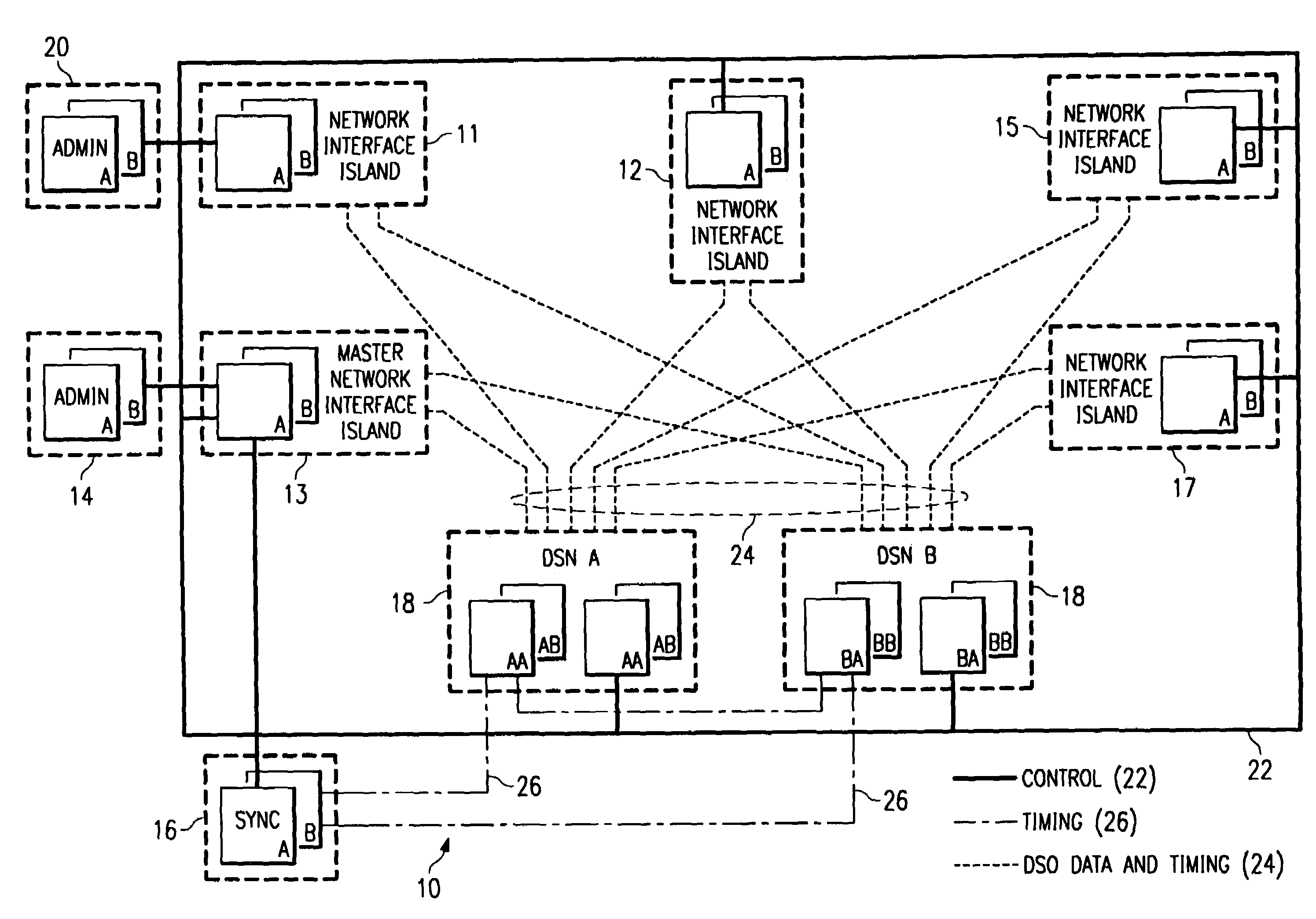
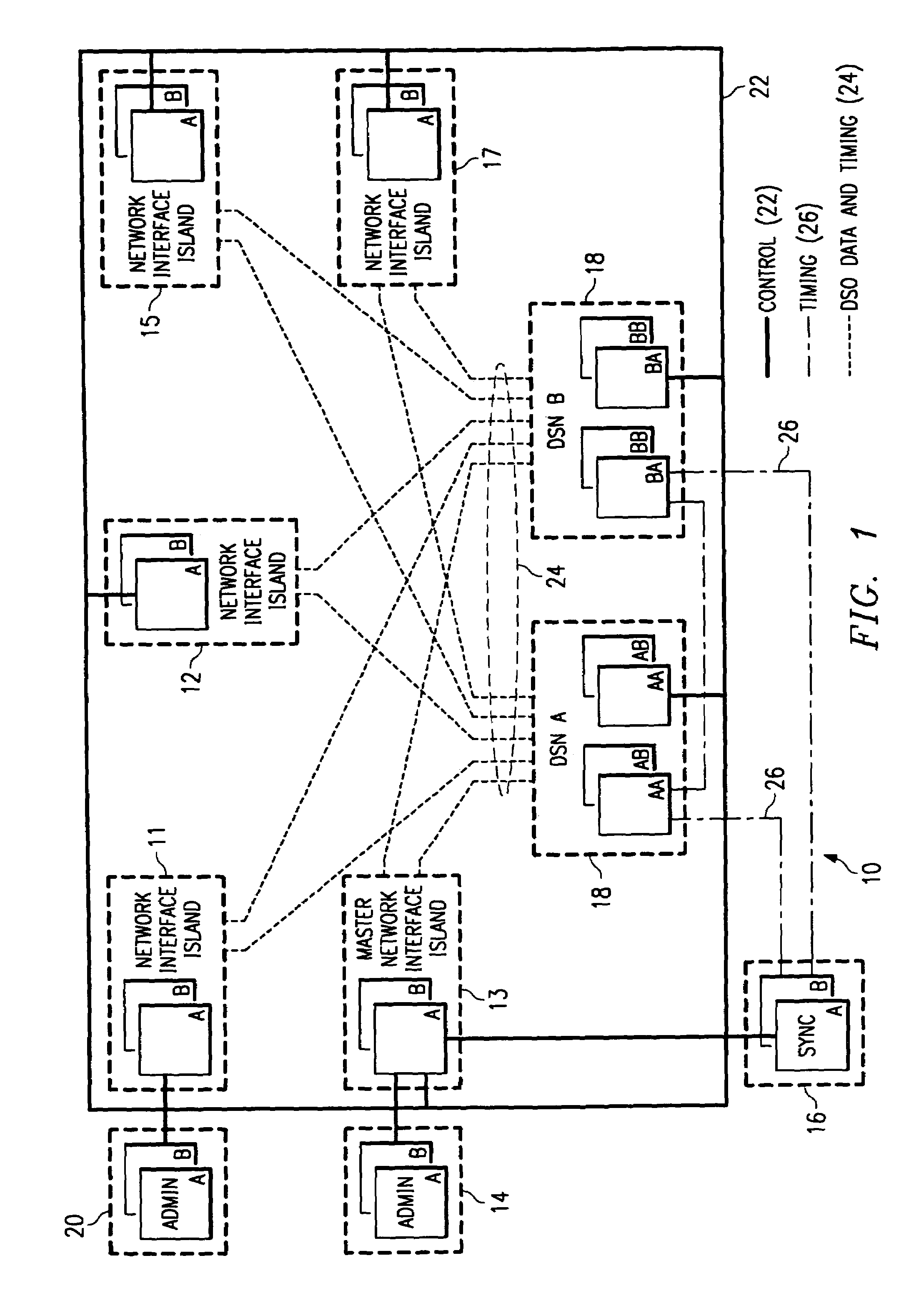
[0026]FIG. 1 is a block diagram of an exemplary system architecture of a distributed digital cross-connect system 10 embodying concepts of the present invention. As shown in FIG. 1, distributed digital cross-connect system 10 includes four network interface islands 11, 12, 15, and 17, a master network interface island 13, an administration subsystem 14, a synchronization subsystem (SYNC) 16, and two distributed services nodes (DSN) 18. Distributed digital cross-connect system 10 also contains provisions for an optional administration subsystem 20. Network interface islands 11, 12, 15, and 17, master network interface island 13, and distributed services nodes 18 are coupled to control system communications media 22. In addition, each network interface island 11, 12, 15, and 17 and master network interface island...


PUM


Abstract

A distributed digital cross-connect system (10) is provided. The system includes two or more network interface islands (12) that connect to the telecommunications network. The system (10) also includes one or more distributed services nodes (18). Each distributed services node (18) connects to two or more of the network interface islands (12). The network interface islands (12) can transmit data to each other through the distributed services node (18). An administration system (14) is also connected to each distributed services node (18) and each network interface island (12). The administration system (14) transmits matrix configuration and telecommunications channel routing data to the network interface islands (12) and the distributed services nodes (18).

Description

RELATED APPLICATION[0001]This application is a continuation of U.S. Ser. No. 08 / 774,155 filed Dec. 26, 1996 now U.S. Pat. No. 6,198,720.TECHNICAL FIELD OF THE INVENTION[0002]This invention relates in general to the field of telecommunication systems, and more particularly to a distributed digital cross-connect system and method.BACKGROUND OF THE INVENTION[0003]Telecommunication systems are operable to connect two or more telecommunications ports through a variety of data transmission media. For example, a first telecommunications port may be coupled to a microwave data transmission medium, which may in turn be coupled to a copper conductor data transmission medium, then to a fiber optic data transmission medium, and subsequently to a second telecommunications port. In this example, telecommunications data is transmitted through a telecommunications channel between the first telecommunications port and the second telecommunications port via the microwave data transmission medium, the...

Claims


Application Information

Patent Timeline
Patent Type & Authority Patents(United States)
IPC IPC(8): H04L12/54H04L12/56
CPCH04L49/1523H04L49/552H04L49/253
Inventor DESCHAINE, STEPHEN A.CROMWELL, MARK C.LOVELACE, GREGORY S.SAMPSON, BECKY J.JETTE, MICHAEL H.SMITH, DENNIS K.MOFFIT, WILLIAM A.SENSEL, STEVEN D.READ, EDGAR L.NOE, AMANDA G.
Owner ALCATEL USA SOURCING
Learn More