Packet switching apparatus including cascade ports and method for switching packets

a packet switching and cascade port technology, applied in the field of data transmission, can solve the problems of increased network traffic, reliability suffers, and potential bottlenecks of nas server and storage device, .g., latency and bandwidth, etc., and achieves the effect of shortening the path, and reducing the number of line cards

Inactive Publication Date: 2006-09-19
AVAGO TECH INT SALES PTE LTD
View PDF17 Cites 98 Cited by
  • Summary
  • Abstract
  • Description
  • Claims
  • Application Information

AI Technical Summary

Benefits of technology

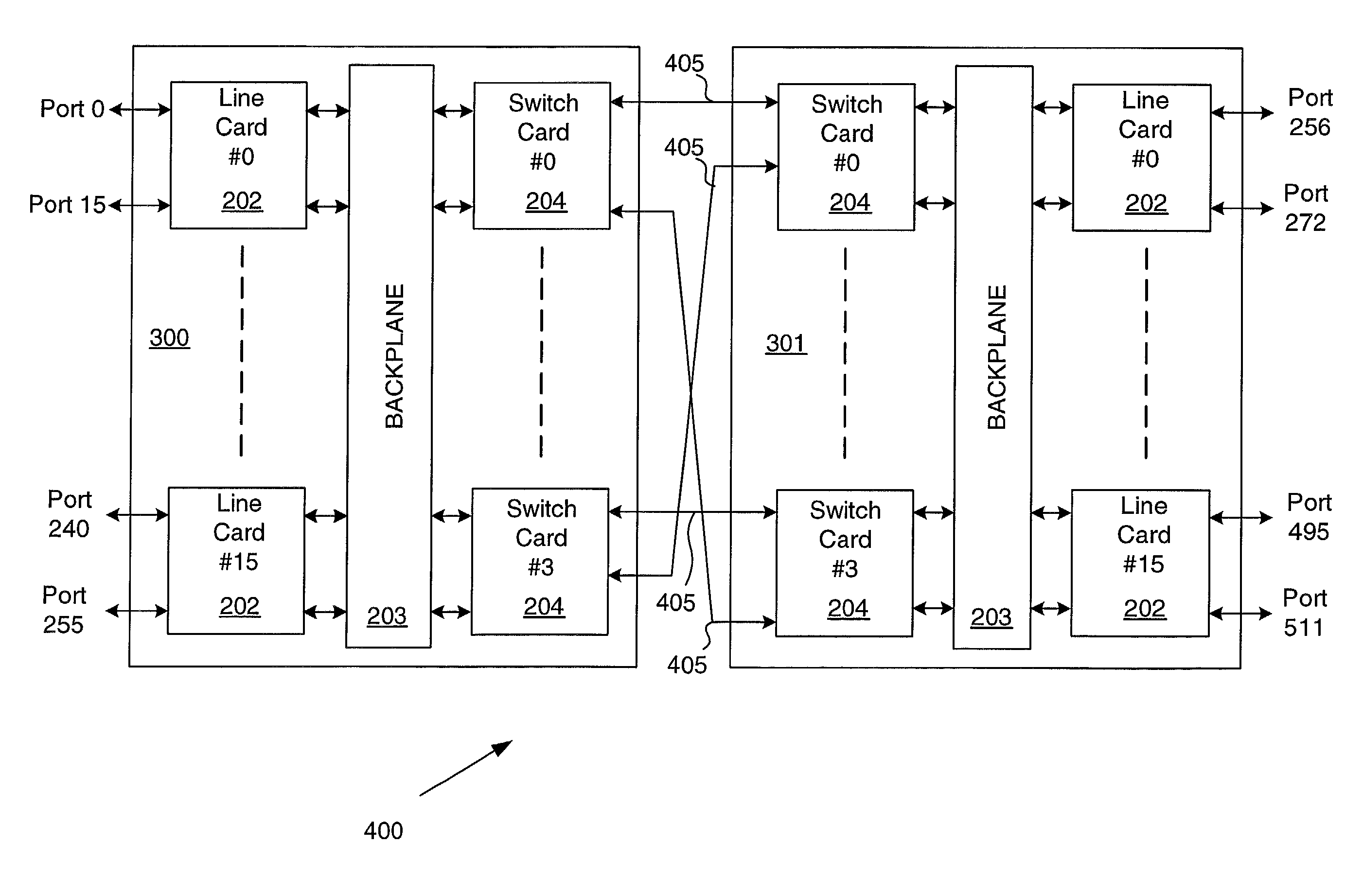
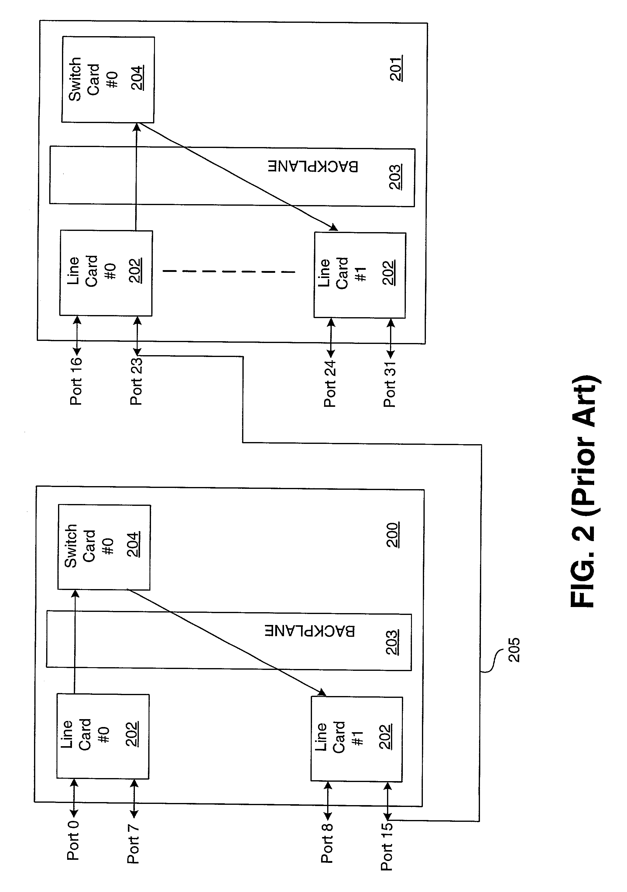
[0013]A switching device comprises at least two base racks, each base rack including a switch card in communication with a line card across a backplane, the line card having at least one port capable of receiving and transmitting a packet. The at least two base racks are coupled such that the switch cards of each are in communication. By allowing for direct communication between switch cards of different base racks, the present invention avoids the use of line card ports to tie together multiple base racks, making these ports available as external ports to link to various devices. Further, by allowing for direct communication between switch cards of different base racks, the present invention also shortens the path that a packet must travel between an input port and a destination port. The path is shortened by reducing the number of line cards the packet must pass through in each base rack.

Problems solved by technology

A shortcoming of a DAS system is that when the server is off-line or not functioning properly, its storage capability and its associated files are unavailable.
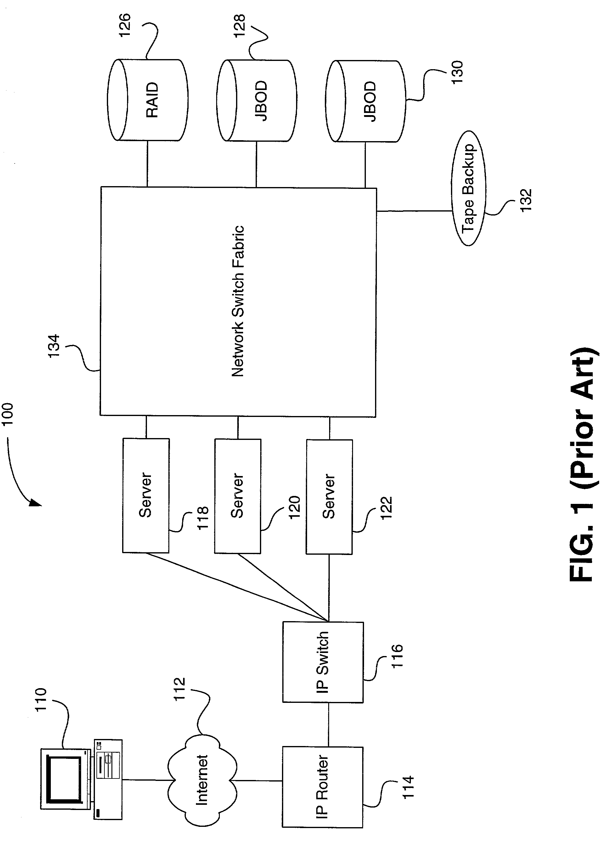
A NAS system typically shares the Local Area Network (LAN) bandwidth, therefore a disadvantage of a NAS system is the increased network traffic and potential bottlenecks surrounding the NAS server and storage devices.
One such challenge is to provide a scalable system wherein thousands of storage devices can be interconnected.
Performance (e.g., latency and bandwidth) and reliability suffer in such an existing solution.
Additionally, a configuration that includes hundreds of interconnected switches is also inherently difficult to manage and to diagnose faults therein, both from a hardware and software perspective.
Still further, since no available SAN protocol is truly ubiquitous enough to be readily integrated with other networking architectures in a heterogeneous SAN environment, bridges and conversion equipment are needed, which increases the cost and management of such a system.

Method used


Image

  • Packet switching apparatus including cascade ports and method for switching packets
  • Packet switching apparatus including cascade ports and method for switching packets
  • Packet switching apparatus including cascade ports and method for switching packets

Examples


Embodiment Construction

[0024]FIG. 3 is a logical diagram illustrating a base rack 300 of the present invention. The base rack 300 includes one or more line cards 202 in communication with one or more switch cards 204 across a backplane 203, and one or more Service Processor Cards (SPC) 305 also in communication via backplane 203. Each line card 202 includes one or more ports 310 for receiving and transmitting packets. Each port 310 is coupled in series first to a Gigabit Interface Converter (GBIC) 320, then to a PHY chip 330, and lastly to a Packet Processing ASIC (PP) 340. The PP 340 is further coupled to SRAM 342, to a Network Processor Unit (NPU) 344 coupled to a DRAM 346, and to the backplane 203. Each switch card 204 includes one or more Flow Control ASICs (FLC) 350 coupled to the backplane 203. Each FLC 350 is coupled to a crossbar 360 and further coupled to a GBIC 320 coupled to a cascade port 370.

[0025]The line card 202 is responsible for all packet processing, as described below, before forwardin...


PUM


Abstract

A switching device comprises at least two base racks, each base rack including a switch card in communication with a line card across a backplane, the line card having at least an external port. The at least two base racks are coupled such that the switch cards of each are linked. A method for switching a packet comprises introducing the packet into an external port on a first base rack, transmitting the packet from a first cascade port on the first base rack to a second cascade port on a second base rack, and sending the packet out of the second base rack through a second external port.

Description

BACKGROUND[0001]1. Field of the Invention[0002]The present invention relates generally to data transmission, and more particularly to packet switching between various devices within a network.[0003]2. Description of the Prior Art[0004]With early networked storage systems, files are made available to the network by attaching storage devices to a server, which is sometimes referred to as Direct Attached Storage (DAS). In such a configuration, the server controls and “owns” all of the data on its attached storage devices. A shortcoming of a DAS system is that when the server is off-line or not functioning properly, its storage capability and its associated files are unavailable.[0005]At least the aforementioned shortcoming in DAS systems led to Network Attached Storage (NAS) technology and associated systems, in which the storage devices and their associated NAS server are configured on the “front-end” network between an end user and the DAS servers. Thus, the storage availability is i...

Claims


Application Information

Patent Timeline
Patent Type & Authority Patents(United States)
IPC IPC(8): H04L12/66H04L12/50
CPCH04L49/15H04L49/25H04L49/40
Inventor CHAMDANI, JOSEPH I.CORWIN, MICHAELROGGE, MATTHEW
Owner AVAGO TECH INT SALES PTE LTD
Why Eureka
Try Eureka