Elevated movable cargo tray for vehicle
- Summary
- Abstract
- Description
- Claims
- Application Information
AI Technical Summary
Benefits of technology
Problems solved by technology
Method used
Image
Examples
Embodiment Construction
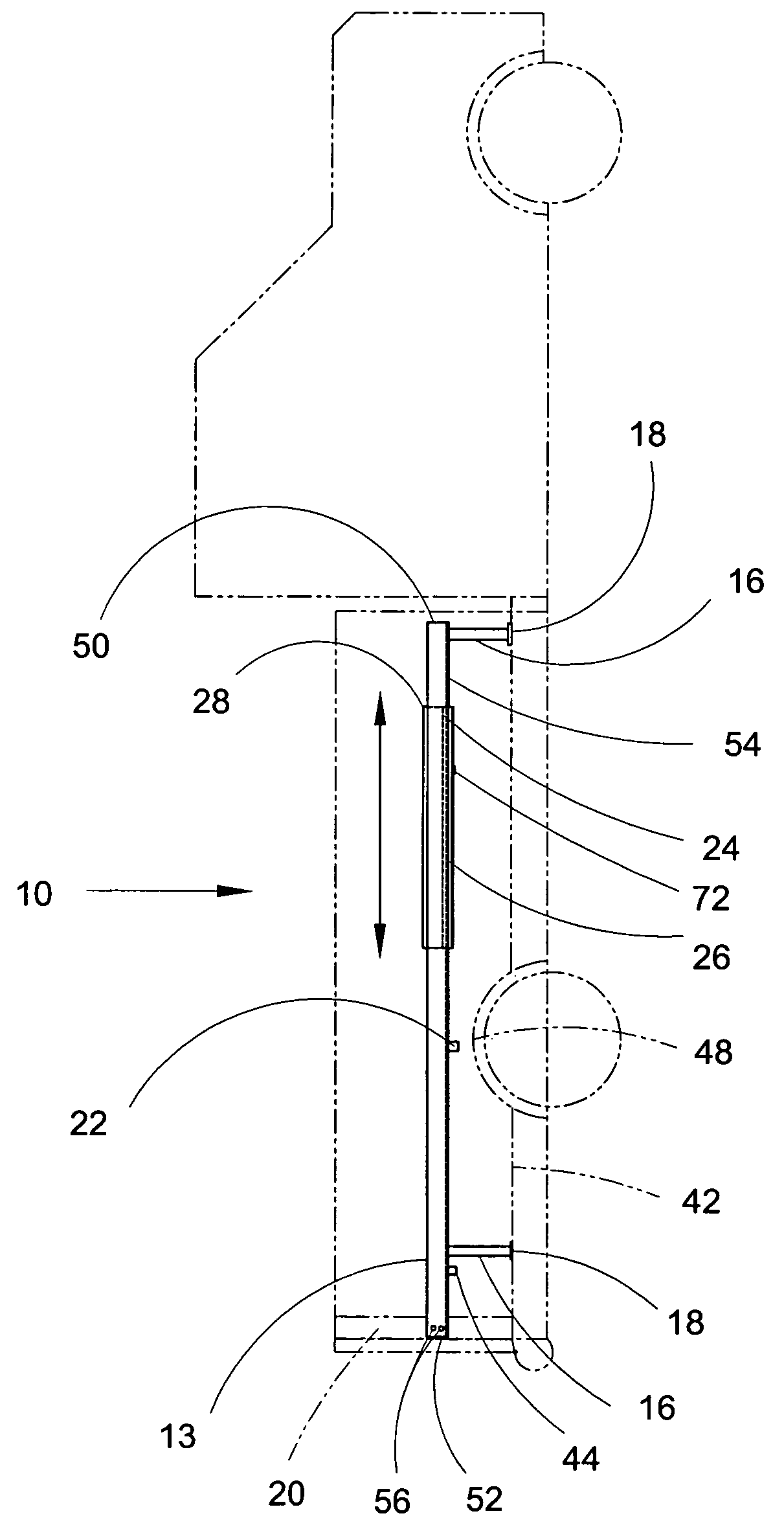
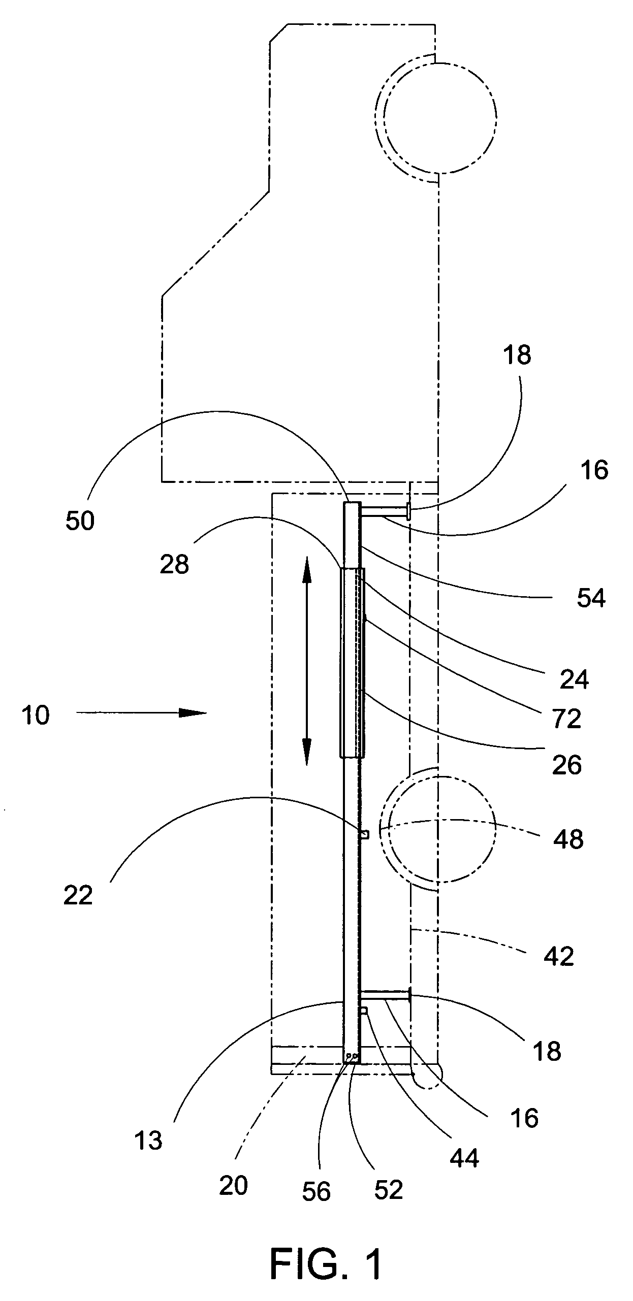
[0035]Cargo tray assembly 10 will now be described, by way of example, with reference to the accompanying drawings. FIGS. 1 through 7B illustrate a preferred embodiment of cargo tray assembly 10 wherein a front-to-rear-position slideable, lockable, and elevated cargo tray that is easy to install and remove is disclosed.
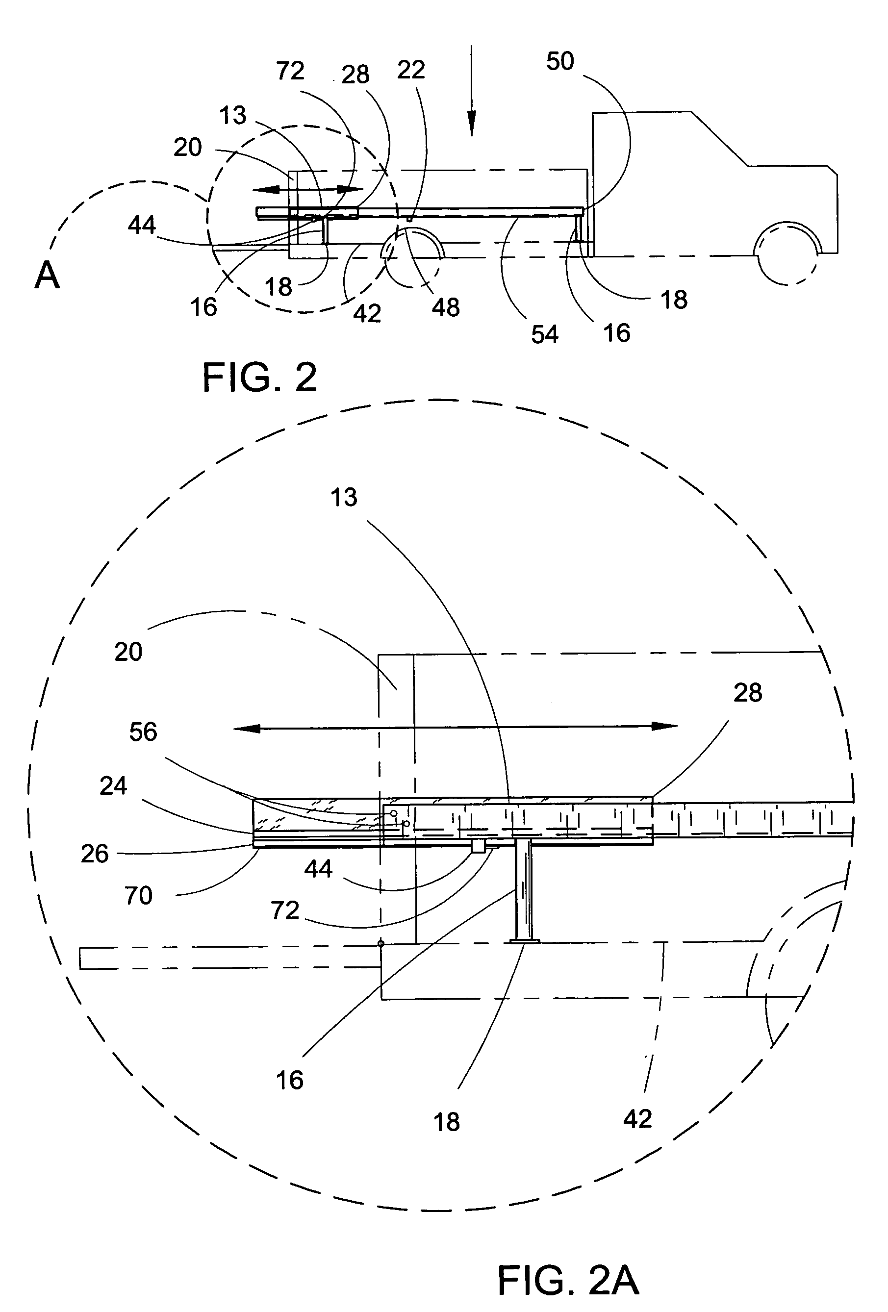
[0036]Turning to FIG. 1, therein is shown a cut away side view of cargo tray assembly 10 mounted in a typical internal fender pickup truck bed that is shown in phantom lines and not a part of this invention. FIG. 2 shows a reduced view similar to FIG. 1 except the tailgate of the pickup truck is down and cargo tray 28 is shown in its rearmost position, cantilevered out of the bed approximately 12 inches. FIG. 2A is an enlarged partial view of cargo tray 28 in its cantilevered position.
[0037]An elevated stationary frame assembly is shown in FIGS. 3 and 3A, comprised of L-shaped opposing left and right side rails 12 and 13 respectively that have first ends 50, second en...
PUM
 Abstract
Description
Claims
Application Information
 - R&D
- Intellectual Property
- Life Sciences
- Materials
- Tech Scout
- Unparalleled Data Quality
- Higher Quality Content
- 60% Fewer Hallucinations
Browse by: Latest US Patents, China's latest patents, Technical Efficacy Thesaurus, Application Domain, Technology Topic, Popular Technical Reports.
© 2025 PatSnap. All rights reserved.Legal|Privacy policy|Modern Slavery Act Transparency Statement|Sitemap|About US| Contact US: help@patsnap.com


