Variable vane electro-graphic thrust washer

a technology of electro-graphic and thrust washer, which is applied in the direction of machines/engines, liquid fuel engines, forging/pressing/hammering apparatuses, etc., can solve the problems of undesirable angular displacement of the variable vane, the inability of the thrust washer to stand up to the high temperatures and loads of the advanced high-performance compressor, etc., and achieves the effect of improving wear characteristics and reducing wear

Active Publication Date: 2006-09-26
RTX CORP
View PDF2 Cites 17 Cited by
  • Summary
  • Abstract
  • Description
  • Claims
  • Application Information

AI Technical Summary

Benefits of technology

[0007]Accordingly, it is an object of the present invention to provide a system for operating a variable vane in a gas turbine engine having improved wear characteristics and more particularly to a thrust washer constructed of electro-graphitic carbon for reducing wear used in said system.
[0008]In accordance with the present invention, a method for improving the wear characteristics of a system for operating a variable vane comprises the steps of providing a trunnion connected to the variable vane via a vane platform and means for causing rotation of the trunnion, and positioning a thrust washer formed from a carbon material about a lower portion of the trunnion and in a space between the vane platform and an outer split case so that during operation of the system the space between the vane platform and the outer split case is maintained substantially constant and unwanted deflection of the vane is avoided.
[0009]In further accordance with the present invention, a system for operating a variable vane in a gas turbine engine comprises a vane, a trunion attached to the vane for rotating the vane, and means for avoiding unwanted deflection of the vane at operating temperatures, the deflection avoiding means comprises a self lubricating thrust washer surrounding a lower portion of the trunnion.

Problems solved by technology

In the past, the thrust washer 23 has been typically constructed of a wear resistant and low friction material such as graphite filled polyimide materials capable of continuous operation up to 650° F. The thrust washers 23 constructed of such polyimide materials are not capable of withstanding the high temperatures and loads of advanced high performance compressors.
Geometric alterations are undesirable because they can result in an undesirable angular displacement of the variable vane 17.

Method used


Image

  • Variable vane electro-graphic thrust washer
  • Variable vane electro-graphic thrust washer

Examples


Embodiment Construction

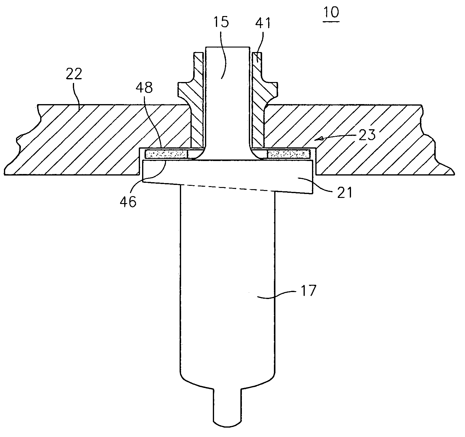
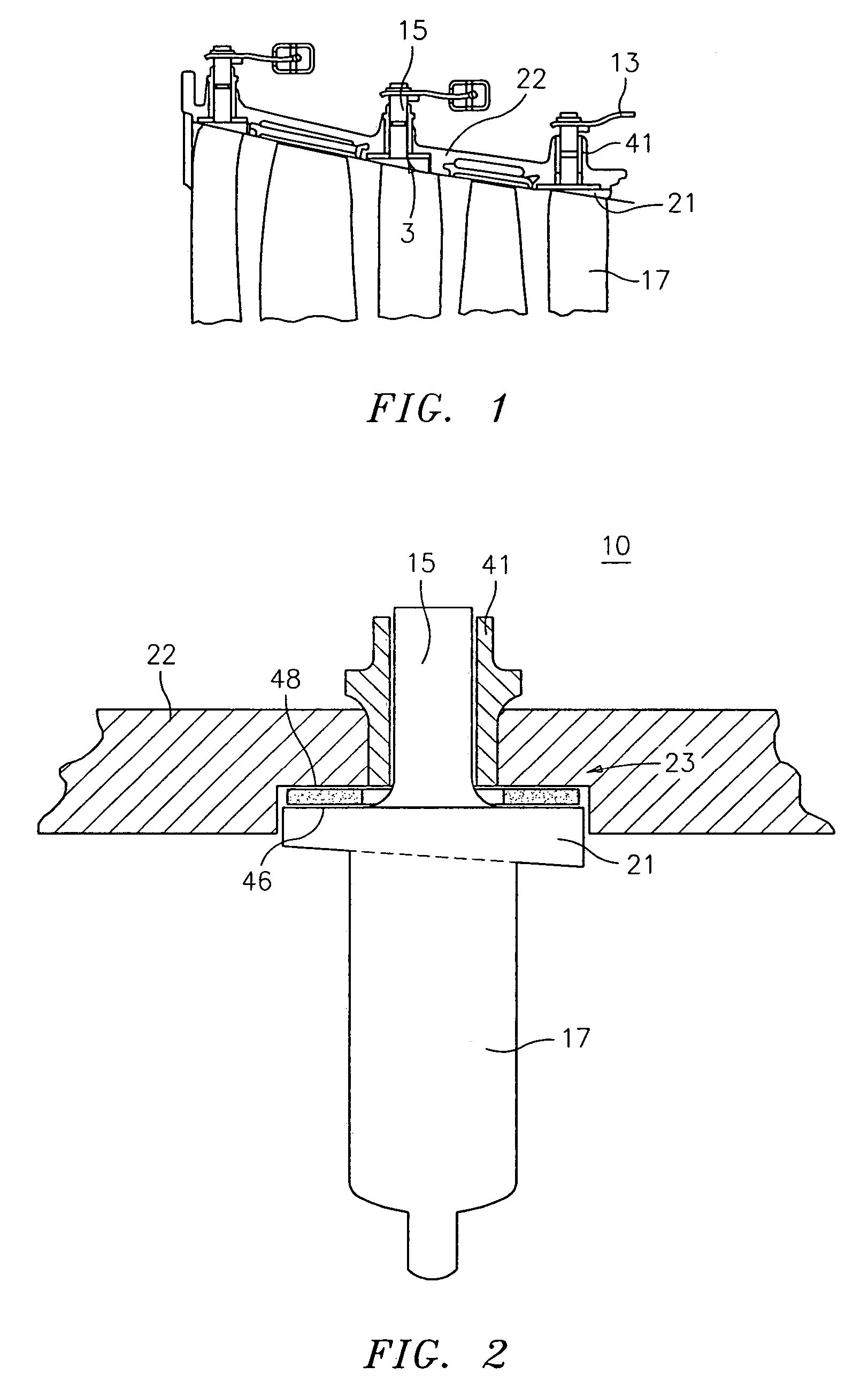
[0012]It is a teaching of the present invention to provide a variable vane operating system having a thrust washer 23 composed of a carbon based substance, preferably electro-graphitic carbon. It has been suprisingly found that the use of such a thrust washer in a variable vane operating system is advantageous in a high temperature environment because the washer does not suffer significant breakdown even at temperatures approximating 1050° F. In addition, a thrust washer formed from such a material both self lubricates as well as maintains the appropriate distance between the vane platform 21 and the outer split case 22. As used herein, “self lubricate” refers to the ability of the thrust washer of the present invention to degrade through a process of depositing the electro-graphitic carbon from which it is constructed onto the engine components with which it is in contact. As a result of this deposition, the volume originally occupied by the thrust washer remains filled with electr...


PUM

PropertyMeasurementUnit
temperatureaaaaaaaaaa
operational temperatureaaaaaaaaaa

Abstract

A method for improving the wear characteristics of a system for operating a variable vane comprising the steps of providing a trunnion connected to the variable vane via an vane platform and means for causing rotation of the trunnion, and positioning a thrust washer formed from a carbon material about a lower portion of the trunnion and in a space between the vane platform and an outer split case so that during operation of the system the space between the vane platform and the outer split case is maintained substantially constant and unwanted deflection of the vane is avoided.

Description

BACKGROUND OF THE INVENTION[0001](1) Field of the Invention[0002]The present invention relates to a system for operating a variable vane in a gas turbine engine having improved wear characteristics and more particularly to a thrust washer constructed of electro-graphitic carbon for reducing wear used in said system.[0003](2) Description of the Related Art[0004]In gas turbine engines, the variable vanes of the high pressure compressor are rotated via a trunnion assembly. With reference to FIG. 1, there is illustrated the construction of a portion of an engine including a trunnion 15. The trunnion 15 is situated between a liner housing 41 and an outer split case 22 and extends to a platform 21 through a thrust washer 23. Variable vane 17 is attached to the trunnion 15 via a vane platform 21.[0005]In the past, the thrust washer 23 has been typically constructed of a wear resistant and low friction material such as graphite filled polyimide materials capable of continuous operation up t...

Claims


Application Information

Patent Timeline
Patent Type & Authority Patents(United States)
IPC IPC(8): F03B3/18F04D29/56F01D17/16F04D29/056F04D29/063
CPCF01D17/162Y10T29/49947Y10T29/49321F04D29/563
Inventor BROOKS, ROBERT T.
Owner RTX CORP
Why Eureka
Try Eureka