Vibrational power generation device vibrator

a power generation device and vibration technology, applied in the direction of electric generator control, electric motor propulsion transmission, piezoelectric/electrostrictive device details, etc., can solve the problems of power generation efficiency reduction or inability of variable-capacitance vibrators, inability to achieve desired capacitance changes, etc., to improve the power generation efficiency of vibrators, reduce the loss of capacity of power generation vibrators, and improve power generation efficiency

Inactive Publication Date: 2006-09-26
HITACHI LTD
View PDF18 Cites 23 Cited by
  • Summary
  • Abstract
  • Description
  • Claims
  • Application Information

AI Technical Summary

Benefits of technology

[0008]An object of the present invention is to provide a vibrational power generation device vibrator capable of remarkably improving the power generation efficiency of capacitance-type vibrational power generation.
[0016](1) By using the oscillation plates parallel to the vibrator, it is possible to reduce loss of capacity of the power generation vibrator and thereby improve the power generation efficiency.
[0017](2) By monitoring operations of the vibrator, it is possible to perform input and output of electric charges at optimum timings and thereby improve the power generation efficiency of the vibrator for power generation.
[0018](3) BY items (1) and (2) as mentioned above, it is possible to realize a vibrational power generator system with high performance and high reliability.

Problems solved by technology

However, the inventors of the present invention have found that the following problem arises in the above-mentioned power generation technique for converting vibrational energy into electric energy.
Therefore, the vibrator performs various operations besides desired operations, whereby desired capacitance changes cannot be obtained due to an influence of the vibration on the capacitance changes.
For this reason, a problem is such that power generation by the variable-capacitance vibrator is reduced in power generation efficiency or cannot be made.

Method used


Image

  • Vibrational power generation device vibrator
  • Vibrational power generation device vibrator
  • Vibrational power generation device vibrator

Examples


first embodiment

[0032

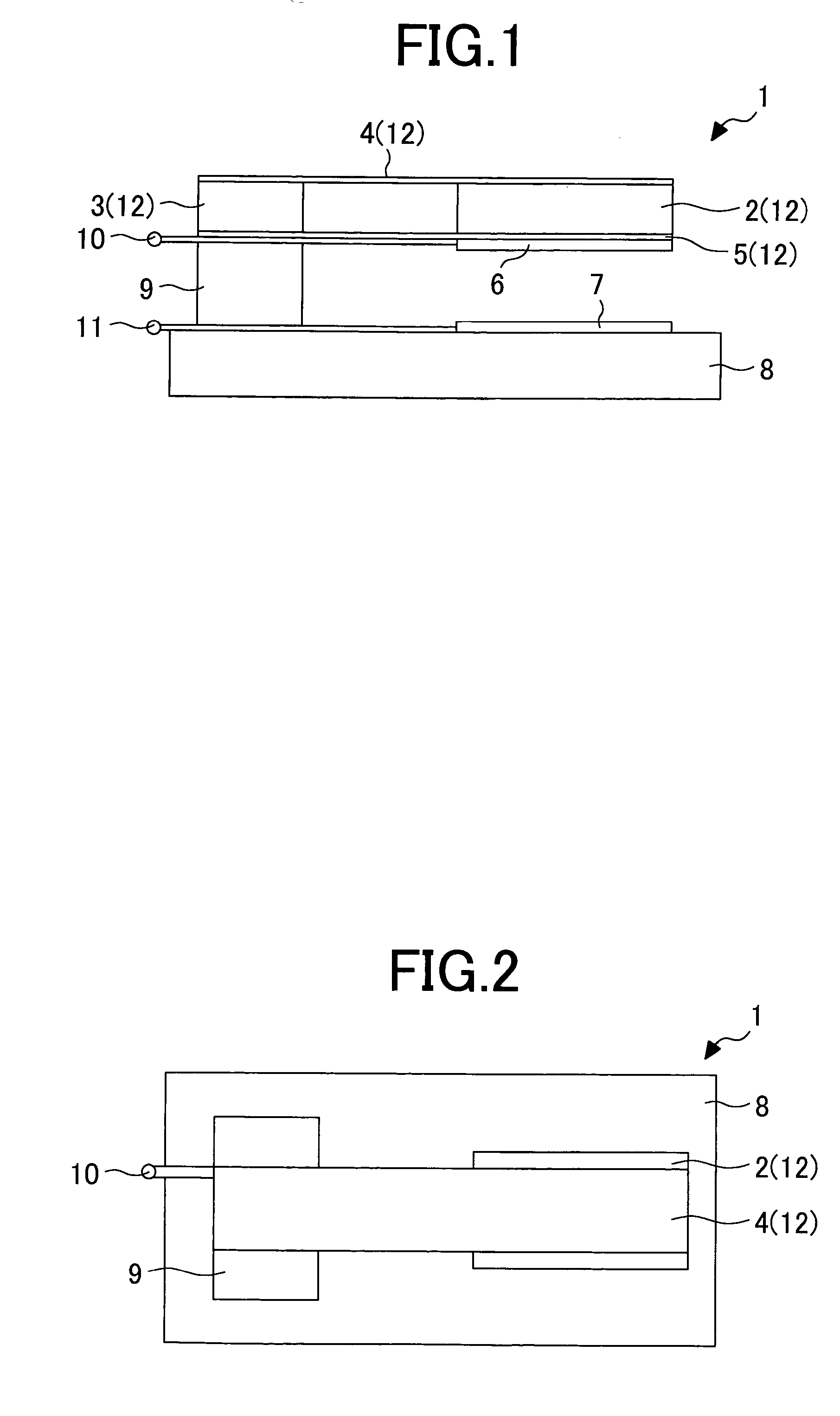
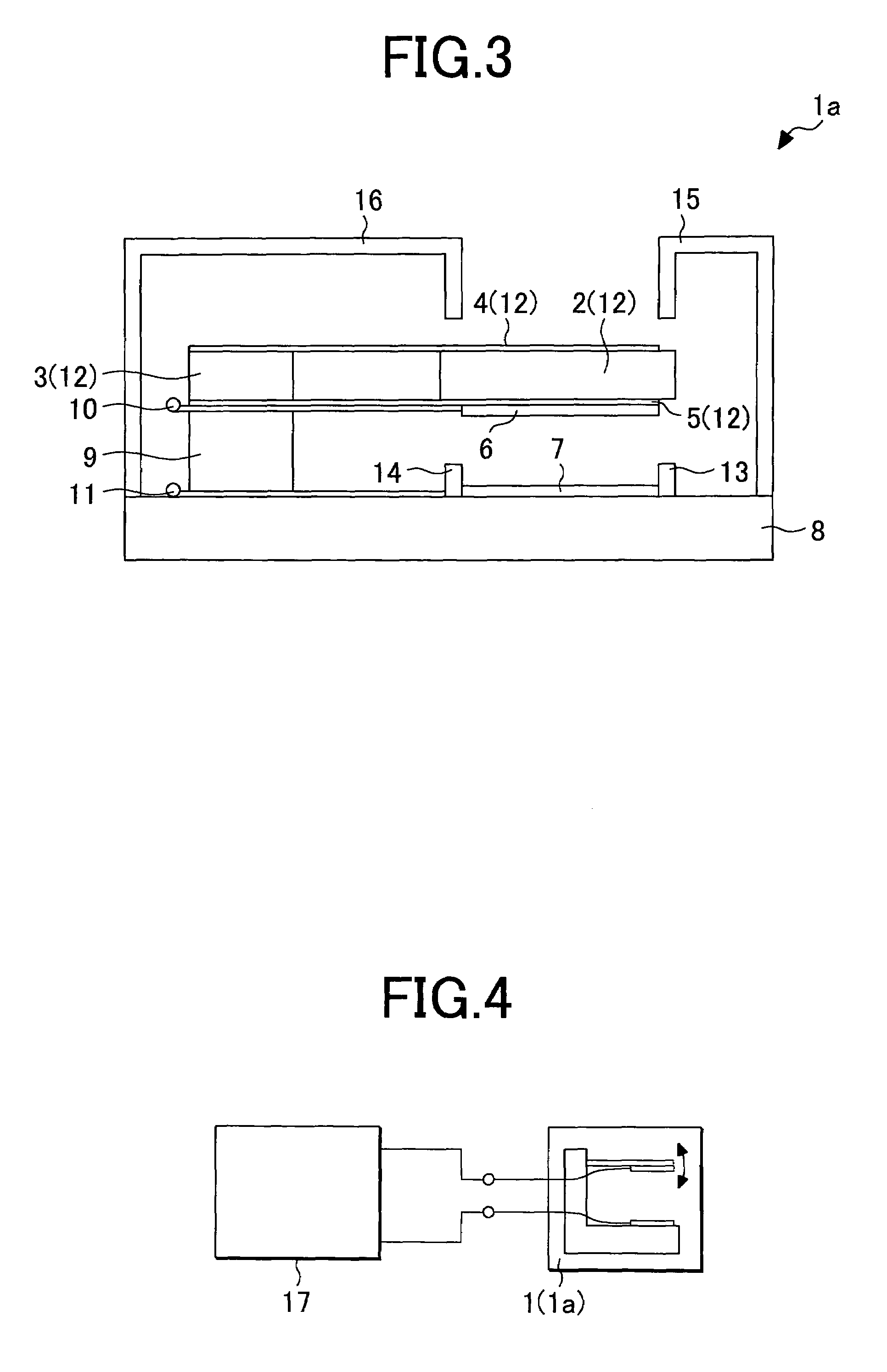
[0033]FIG. 1 is a side view showing a structure of a variable-capacitance type vibrator according to a first embodiment of the present invention; FIG. 2 is a top view of the variable-capacitance type vibrator in FIG. 1; FIG. 3 is a side view showing another structure of a variable-capacitance type vibrator according to a first embodiment of the present invention; and FIG. 4 is a block view showing an example of vibrational power generator system according to a first embodiment of the present invention.

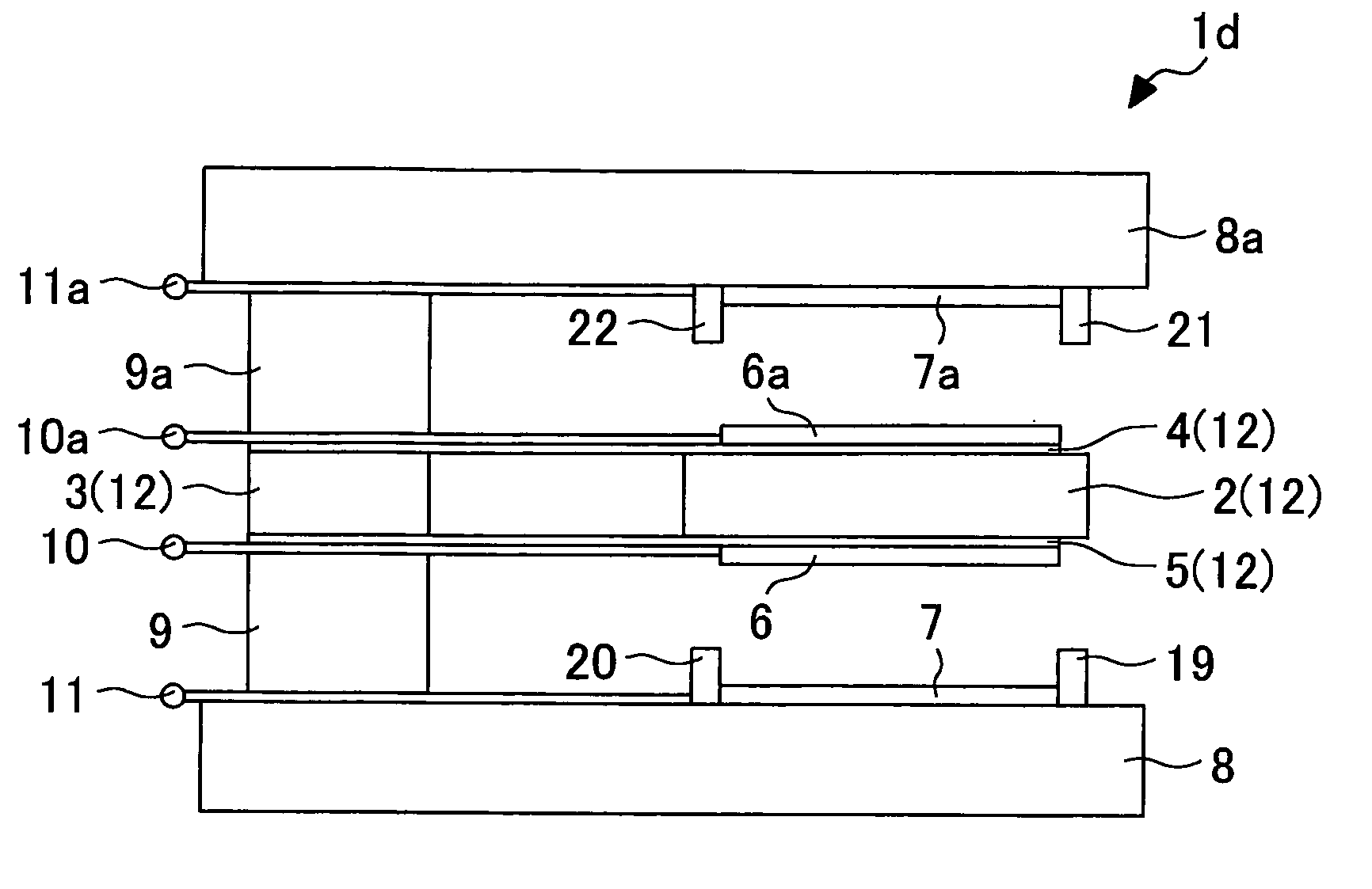
[0034]In a first embodiment, a variable-capacitance type vibrator (vibrational power generation device vibrator) 1 comprises, as illustrated in FIG. 1, a mass 2, a spacer 3, oscillation plates 4 and 5, electrodes 6 and 7, an opposite electrode base 8, a vibrator pedestal 9, and electrode wiring terminals (electrode terminals) 10 and 11.

[0035]The oscillation plates 4 and 5 are each formed into, for example, a rectangular plate, and the mass 2 is sandwiched between one ends of the o...

second embodiment

[0063

[0064]FIG. 5 is a side view showing a structure of a variable-capacitance type vibrator according to a second embodiment, and FIG. 6 is a top view of the variable-capacitance type vibrator in FIG. 5.

[0065]In a second embodiment, a variable-capacitance type vibrator (vibrational power generation device vibrator) 1b comprises, as illustrated in FIG. 5, a mass 2, a spacer 3, oscillation plates 4 and 5, electrodes 6 and 7, an opposite electrode base 8, a vibrator pedestal 9, and electrode wiring terminals 10 and 11, and a difference between the present embodiment and the first Embodiment shown in FIG. 1 is that the oscillation plates 4 and 5 are comprised of a plurality of oscillation plates 41 to 4n and 51 to 5n.

[0066]FIG. 6 is a top view of the variable-capacitance type vibrator 1b.

[0067]As illustrated, the oscillation plates 41 to 4n and 51 to 5n are arranged so as to sandwich the mass 2 and the spacer 3 between them at equal intervals. The number of respective oscillation plat...

third embodiment

[0073

[0074]FIG. 7 is a side view showing a structure of a variable-capacitance type vibrator according to a third embodiment, and FIG. 8 is a top view of the variable-capacitance type vibrator in FIG. 7.

[0075]In a third embodiment, a variable-capacitance type vibrator (vibrational power generation device vibrator) 1c comprises, as illustrated in FIG. 7, a plurality of masses 21 to 2n-1, a plurality of spacers 31 to 3n-1, a plurality of oscillation plates 181 to 18n, electrodes 6 and 7, an opposite electrode base 8, a vibrator pedestal 9, and electrode wirings 10 and 11.

[0076]The oscillation plate(s) 181 (to 18n) has / have the same shape as that of the oscillation plate 4 as illustrated in FIG. 1 in the first embodiment, and the masses 21 to 2n-1 and the spacers 31 to 3n-1 are respectively sandwiched between the oscillation plates 181 to 18n.

[0077]For example, the mass 21 and the spacer 31 are sandwiched between the oscillation plate 181 and the oscillation plate 182, and the mass 22 ...


PUM


Abstract

Unnecessary moment in a vibrator is remarkably reduced and the power generation efficiency in capacitance-type vibrational power generation is remarkably improved. A vibrator provided in a variable-capacitance type vibrator has a structure in that one ends of oscillation plates extending in a longitudinal direction thereof sandwiches a mass and the other ends thereof sandwiches a spacer, respectively, wherein the oscillation plates are arranged parallel to each other. A space portion between the oscillation plates and in which the mass and the spacer are not in contact with each other functions as a spring. By holding the mass by the two oscillation plates, the mass can be oscillated while it is in parallel to an opposing electrode. Therefore, generation of unnecessary moment in a direction other than an oscillation direction can be remarkably reduced.

Description

BACKGROUND OF THE INVENTION[0001]The present invention relates to a power generation technology for converting mechanical vibrational energy into electric energy, and particularly to a technique effectively applied to variable-capacitance type vibrational power generation in which variable capacitances are changed by the vibrational energy to perform power generation.[0002]For example, IEEE Trans. VLSI Systems, pp. 64–76, Vol. 9, no. 1, 2001 (Non-patent Document 1) discloses a technique for performing power generation by the vibrational energy, the technique in which: electrodes are provided at a fixed end of a vibrator operating in resonance with the vibrational energy; a variable capacitance capable of realizing valiance of capacitance by changing a distance between the electrodes depending on the operation of the vibrator is used; electric charges are applied to the electrodes of the variable capacitance; the Coulomb attraction is exerted between the opposing electrodes through t...

Claims


Application Information

Patent Timeline
Patent Type & Authority Patents(United States)
IPC IPC(8): H02N1/00F02B63/04F03G7/08H01L41/04H02N2/00B60L50/10B61C9/38H02P9/04
CPCH02N1/006
Inventor TANAKA, HIDETOSHIOHKUBO, NORIOKANETOMO, MASAFUMI
Owner HITACHI LTD
Why Eureka
Try Eureka